ROHM 2SAR554R datasheet user manual
Summary
This datasheet provides comprehensive technical specifications for the 2SAR554R, a high-speed medium power PNP transistor designed for robust switching applications rated at -80V and -1.5A. The manual is essential documentation for electronic engineers and circuit designers who require detailed performance parameters, including saturation voltage curves, DC/AC current gain characteristics, dynamic timing data (turn-on/fall times), and package specifications. Utilize this resource to select the optimal component for reliable and efficient power management circuits.
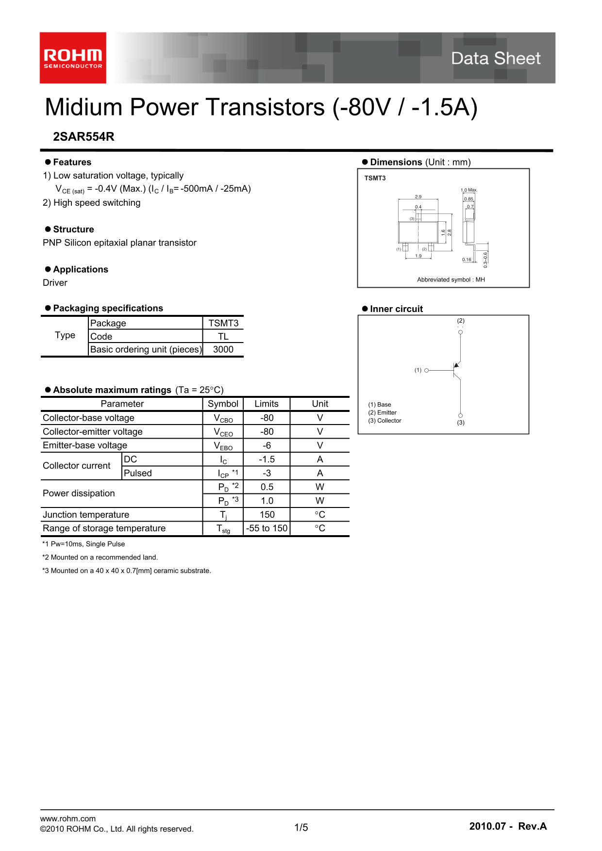
Page 1 Text Content
Midium Power Transistors (-80V / -1.5A) 2SAR554R Features Dimensions (Unit : mm) 1) Low saturation voltage, typically TSMT3 VCE (sat) = -0.4V (Max.) (IC / IB= -500m A / -25m A) 2) High speed switching
Structure PNP Silicon epitaxial planar transistor
Applications
Abbreviated symbol : MH
Driver
Packaging specifications Inner circuit
(2) Package TSMT3 (3)
Type Code TL Basic ordering unit (pieces)
Absolute maximum ratings (Ta = 25C)
Parameter Symbol Limits Unit (1) Base (2) Emitter
Collector-base voltage VCBO -80 (3) Collector
Collector-emitter voltage VCEO -80 Emitter-base voltage VEBO -6
DC IC -1.5
Collector current
Pulsed ICP *1 -3 PD *2 0.5
Power dissipation
PD *3 1.0
Junction temperature Tj C Range of storage temperature Tstg -55 to 150 C *1 Pw=10ms, Single Pulse *2 Mounted on a recommended land. *3 Mounted on a 40 x 40 x 0.7[mm] ceramic substrate.
www.rohm.com
©2010 ROHM Co., Ltd. All rights reserved. 1/5 2010.07 - Rev.A
Page Summary Contents For ROHM 2SAR554R datasheet user manual
Manual Details
| Brand | ROHM |
|---|---|
| Pages | 6 |
| File Size | 328.03 KB |
| Published | July 15, 2026 |
Enter the captcha to get the download link:

Frequently Asked Questions
What is the maximum continuous collector current rating?
The DC Collector Current (I C) limit is -1.5 A, although a pulsed rating of -3 A is specified.
Does this transistor require special mounting conditions?
Yes; reliable power dissipation requires mounting the component on a 40 x 40 x 0.7[mm] ceramic substrate.
Is this part suitable for life-critical equipment or medical devices?
No, it is not designed for systems requiring an extremely high level of reliability where failure could pose a direct threat to human life.
How is the typical collector saturation voltage determined?
The datasheet shows that Vce(sat) is typically -0.4V when operated at I = -500mA and I = -25mA.