OMRON FL Series Lighting for Image Processing FL-STC Lighting Controller Instruction Sheet
Summary
This comprehensive manual provides technical guidance for the FL-STC series Lighting Controller. Designed for industrial automation professionals, it details installation procedures, wiring specifications, and operational settings for controlling linear lighting systems. The guide covers multiple control modes—including PWM frequency adjustments and external trigger inputs—and includes critical information on power requirements (DC24V), I/O management, safety precautions, and comprehensive error code troubleshooting to ensure stable system integration within industrial setups.
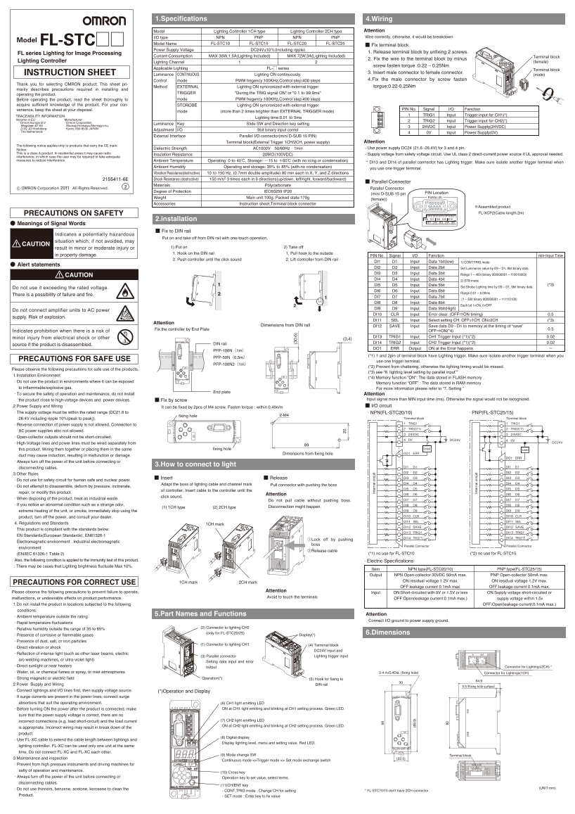
Page 1 Text Content
1.Specifications 4.Wiring
Model Lighting Controller 1CH type Lighting Controller 2CH type Attention I/O type NPN PNP NPN PNP Wire correctly, otherwise, it would be breakdown
Model FL-STC□□
Model Name FL-STC10 FL-STC15 FL-STC20 FL-STC25
■ Fix terminal block
Power Supply Voltage DC24V±10%(Including ripple)
1. Release terminal block by unfixing 2 screws.
FL series Lighting for Image Processing
Currant Consumption MAX 36W,1.5A(Lighting Included) MAX 72W,3A(Lighting Included) Terminal block
2. Fix the wire to the terminal block by minus
Lighting Controller Lighting Channel (female)
screw fasten torque :0.22 – 0.25Nm
Applicable Lighting FL-□ series
Terminal block
INSTRUCTION SHEET 3. Insert male connector to female connector.
Luminance CONTINUOUS Lighting ON continuously. (male)
Control mode PWM fregency:100KHz,Control step:400 steps 4.Fix the male connector by screw fasten
Thank you for selecting OMRON product. This sheet pri-
Method EXTERNAL Lighting ON syncronized with external trigger torgue:0.22-0.25Nm
marily describes precautions required in installing and
TRIGGER "During the TRIG signal ON" or "0.1 to 99.9ms"
operating the product.
Before operating the product, read the sheet thoroughly to mode PWM fregency:100KHz,Control step:400 steps
acquire sufficient knowledge of the product. For your con- STOROBE Lighting ON syncronized with external trigger
venience, keep the sheet at your disposal. PIN No. Signal I/O Fanction
mode (more than 2 times brighter than EXTERNAL TRIGGER mode)
TRACEABILITY INFORMATION: TRIG1 Input Trigger input for CH1(*)
Lighting time:0.01 to 5ms
Importer in EU Manufacturer
TRIG2 Input Trigger input for CH2(*)
Omron Europe B.V. Omron Corporation, Luminance Key Slide SW and Direction key setting Wegalaan 67-69 Shiokoji Horikawa,Shimogyo-ku, 24VDC Input Power Supply(24VDC) 2132 JD Hoofddorp, Kyoto, 600-8530 JAPAN
Adjustment I/O 9bit binary input contol
The Netherlands 0V Input Power Supply(0V)
External Interface Parallel I/O connector(mini D-SUB 15 PIN)
Terminal block(External Trigger 1CH/2CH, power supply) Attention Dielectric Strength AC1000V 50/60Hz 1min - Use power supply DC24 (21.6 -26.4V) for 3 and 4 pin. Insulation Resistance 20MΩ(100VDC) - Supply voltage from safety voltage circuit. Use UL class 2 direct-current power source if UL approval needed.
Ambient Temperature Operating: 0 to 40℃, Storage: -15 to +60℃ (with no icing or condensation)
* DI13 and DI14 of parallel connector has Lighting trigger. Make sure isolate another trigger terminal when
Ambient Humidity Operating and storage: 35% to 85% (with no condensation)
you use one trigger terminal.
Vibration Resistance(destructive) 10 to 150 Hz, (0.7mm double amplitude) 80 min each in X, Y, and Z directions 2155411-6E Shock Resistance (destructive) 150 m/s2 3 times each in 6 directions(up/down, left/right, forward/backward)
■ Parallel Connector
Materials Polycarbonate
Parallel Connector
Degree of Protection IEC60259 IP20 PIN Location
(mini D-SUB 15 pin
Weight Main unit:100g, Packed state:170g PARALLEL
(female))
Accessories Instruction sheet,Terminal block connector
※Assembled product PRECAUTIONS ON SAFETY FL-XCP2(Cable length:2m)
DI11 DI12 DI13 DO1DI14 2.Installation DI6 DI7 DI8 DI10DI9 DI1 DI2 DI3 DI4 DI5
● Meanings of Signal Words
■ Fix to DIN rail
Indicates a potentially hazardous
Put on and take off from DIN rail with one-touch operation.
situation which, if not avoided, may
CAUTION
result in minor or moderate injury or 1) Put on 2) Take off 1. Hook on the DIN rail 1. Pull hook to the outside
in property damage. PIN No. Signal I/O Fanction min-Input Time
2. Push controller until the click sound 2. Lift controller from DIN rail
DI1 D1 Input Data 1bit(low) 1) CONT/TRIG mode
● Alert statements
DI2 D2 Input Data 2bit Set Luminance value by D9 – D1, 9bit binary data. DI3 D3 Input Data 3bit Range 1 – 400 (binary 000000001 – 110010000)
CAUTION
DI4 D4 Input Data 4bit
2) STB mode
DI5 D5 Input Data 5bit (*3)
Do not use it exceeding the rated voltage. Set Strobe Lighting time by D9 – D1, 9bit binary data.
DI6 D6 Input Data 6bit
Range 0.01 – 5.00ms
There is a possibility of failure and fire. (3 0. 6)
DI7 D7 Input Data 7bit
(1 – 500 binary 000000001 – 111110100)
DI8 D8 Input Data 8bit
Each bit 1=ON, 0=OFF
DI9 D9 Input Data 9bit(High)
Do not connect amplifier units to AC power
DI10 CLR Input Error clear. (OFF⇒ON timing) 0.5
supply. Risk of explosion.
DI11 SEL Input Select setting CH. OFF=1CH, ON=2CH (*3)
Attention
· Dimensions from DIN rall DI12 SAVE Input Save data D9 - D1 to memory at the timing of “save”
Fix the controller by End Plate 0.5
Indicates prohibition when there is a risk of OFF⇒ON(*4)
minor injury from electrical shock or other DI13 TRIG1 Input CH1 Trigger Input (*1)(*2) 0.02
DIN rail DI14 TRIG2 Input CH2 Trigger Input (*1)(*2) 0.02
source if the product is disassembled.
DO1 ERR Output ON at the Error happens
PFP-100N(1m)
(*1) 1 and 2pin of terminal block have Lighting trigger. Make sure isolate another trigger terminal when you
PFP-50N(0.5m)
PRECAUTIONS FOR SAFE USE use one trigger terminal.
PFP-100N2(1m)
(*2) Prevent from chattering, otherwise the lighting timing would be missed.
Please observe the following precautions for safe use of the products.
(*3) see “8. lighting level setting by parallel input””
1.Installation Environment In te rn al irc ui
(*4) Memory function “ON”: The data stored in FLASH memory .
· Do not use the product in environments where it can be exposed
Memory function “OFF” : The data stored in RAM memory .
to inflammable/explosive gas. For more information please refer to “7. Setting ”
End plate
· To secure the safety of operation and maintenance, do not install Attention
the product close to high-voltage devices and power devices. ■ Fix by screw Input signal more than MIN input time (ms). Otherwise the signal would not be recognized. 2.Power Supply and Wiring It can be fixed by 2pcs of M4 screw. Fasten torque : within 0.49n/m ■ I/O circuit
· The supply voltage must be within the rated range (DC21.6 to · NPN(FL-STC20/10) · PNP(FL-STC25/15)
(8 9. 9) fixing hole 2-M4
26.4V including ripple 10%(peak to peak)). Terminal block Terminal block · Reverse connection of power supply is not allowed. Connection to TRIG1 TRIG1
TRIG2(*1) TRIG2(*2)
AC power supplies also not allowed.
24VDC 24VDC
· Open-collector outputs should not be short-circuited.
0V DC24V 0V
· High-Voltage lines and power lines must be wired separately from DC24V
this product. Wiring them together or placing them in the same fixing hole Load Load
Dimensions from fixing hole DO1 ERR
duct may cause induction, resulting in malfunction or damage.
DO1 ERR
· Always turn off the power of the unit before connecting or
3.How to connect to light
disconnecting cables. DI1 D1 DI1 D1 DI2 D2 DI2 D2
3.Other Rules
In te rn al irc ui DI3 D3 DI3 D3
■ Insert ■ Release
· Do not use for safety circuit for human safe and nuclear power.
Adapt the boss of lighting cable and channel mark DI4 D4 DI4 D4
· Do not attempt to disassemble, deform by pressure, incinerate, Pull connector with pushing the boss
DI5 D5 DI5 D5
of controller. Insert cable to the controller until the
repair, or modify this product.
Attention DI6 D6 DI6 D6
click sound.
· When disposing of the product, treat as industrial waste. DI7 D7 DI7 D7
Do not pull cable without pushing boss.
· If you notice an abnormal condition such as a strange odor, DI8 D8 DI8 D8
(1) 1CH type (2) 2CH type Disconnection might happen.
extreme heating of the unit, or smoke, immediately stop using the DI9 D9 DI9 D9 product, turn off the power, and consult your dealer. DI10 CLR DI10 CLR DI11 SEL DI11 SEL
4. Regulations and Standards 1CH mark
DI12 SAVE DI12 SAVE
This product is compliant with the standards below:
DI13 TRIG1 DI13 TRIG1
EN Standards(European Standards), EN61326-1
DI14 TRIG2(*1) DI14 TRIG2(*2)
①Lock off by pushing
Electromagnetic environment : Industrial electromagnetic
boss Parallel Connector Parallel Connector
environment
②Release cable
(EN/IEC 61326-1 Table 2) (*1) no use for FL-STC10 (*2) no use for FL-STC15
Also, the following condition is applied to the immunity test of this product. · Electric Specifications : There may be cases that Lighting brightness fluctuate Max 10%.
Item NPN type(FL-STC20/10) PNP type(FL-STC25/15) Output NPN Open-collector 30VDC 50m A max. PNP Open-collector 50m A max. ON:residual voltage 1.2V max. ON:residual voltage 1.2V max.
PRECAUTIONS FOR CORRECT USE 1CH mark 2CH mark
OFF:leakage current 0.1m A max. OFF:leakage current 0.1m A max.
Please observe the following precautions to prevent failure to operate, Attention
Input ON:Short-circuited with 0V or 1.5V or less ON:Supply voltage short-circuited or
malfunctions, or undesirable effects on product performance. Avoid to touch the terminals
OFF:Open(leakage current:0.1m A max.) supply voltage within 1.5v
1.Do not install the product in locations subjected to the following OFF:Open(leakage current:0.1m A max.) conditions:
5.Part Names and Functions Attention
· Ambient temperature outside the rating
Connect I/O ground to power supply ground.
· Rapid temperature fluctuations
(2) Connector to lighting CH2
· Relative humidity outside the range of 35 to 85%
(only for FL-STC20/25) 6.Dimensions
· Presence of corrosive or flammable gases Display(*)
· Presence of dust, salt, or iron particles
(1) Connector to lighting CH1 (4) Terminal block
· Direct vibration or shock
DC24V input and
· Reflection of intense light (such as other laser beams, electric
(3) Parallel connector Lighting trigger input
arc-welding machines, or ultra-violet light)
Setting data input and error
· Direct sunlight or near heaters output Connector for Lightings(2CH) * · Water, oil, or chemical fumes or spray, or mist atmospheres 2-4.4×5.4Dia. (fixing hole) Connector for Lightings(1CH)
· Strong magnetic or electric field Operation(*) (5) Hook for fixing to
2.Power Supply and Wiring DIN rail
5.5(Fixing hole surface)
· Connect lightings and I/O lines first, then supply voltage source. (*)Operation and Display · If surge currents are present in the power lines, connect surge absorbers that suit the operating environment. (6) CH1 light emitting LED
· Before turning ON the power after the product is connected, make ON at CH1 light emitting and blinking at CH1 setting process. Green LED.
sure that the power supply voltage is correct, there are no
incorrect connections (e.g. load short-circuit) and the load current (7) CH2 light emitting LED ON at CH2 light emitting and blinking at CH2 setting process. Green LED.
is appropriate. Incorrect wiring may result in break down of the product.
(8) Digital display
· Use FL-XC cable to extend the cable length between lightings and
Display lighting level, menu and setting value. Red LED.
lighting controller. FL-XC can be used only one unit at the same time. Do not connect FL-XC and FL-XC each other.
(9) Mode change SW Terminal block
3.Maintenance and inspection (22.5)
Continuous mode <>Trigger mode <> Set mode exchange switch
· Prevent from high pressure instruments and driving machines for safty of operation and maintenance.
(10) Cross key
· Always turn off the power of the unit before connecting or Operation key to set value, select terms. disconnecting cables.
(11)CH/ENT key
· Do not use thinners, benzene, acetone, kerosene to clean the (UNIT:mm)
- CONT,TRIG mode : Change CH for setting * FL-STC10/15 don’t have 2CH connector.
Product. - SET mode : Enter key to fix value
Page Summary Contents For OMRON FL Series Lighting for Image Processing FL-STC Lighting Controller Instruction Sheet
Manual Details
| Brand | Image |
|---|---|
| Pages | 2 |
| File Size | 534.70 KB |
| Published | June 03, 2026 |
Enter the captcha to get the download link:

Frequently Asked Questions
What is the required input power supply voltage?
The system requires a DC24V±10% (including ripple) power supply.
How do I install the lighting controller on a DIN rail?
Hook it onto the DIN rail, then push the controller until you hear a click sound. Be careful when removing it.
What is the connection for a manual trigger input (CH1)?
Use the PIN No. 13 terminal labeled TRIG1 for the CH1 Trigger Input.
What are the recommended wire fastening values?
The screw fasten torque for the lighting controller terminal block is specified as 0.22 – 0.25Nm.