Netgear APS135W - ProSAFE 135W Auxiliary Power Supply Install Guide
Summary
This guide provides comprehensive instructions for handling the APS135W ProSafe Auxiliary Power Supply module. This hot-swappable power unit is designed to maintain reliable operation for GSM73xxSv2 series gigabit switches, allowing replacement without system downtime or rebooting. Perfect for network technicians and IT professionals responsible for critical data center infrastructure, this manual details safe installation procedures, effective removal steps, and best practices for uninterrupted switch maintenance.
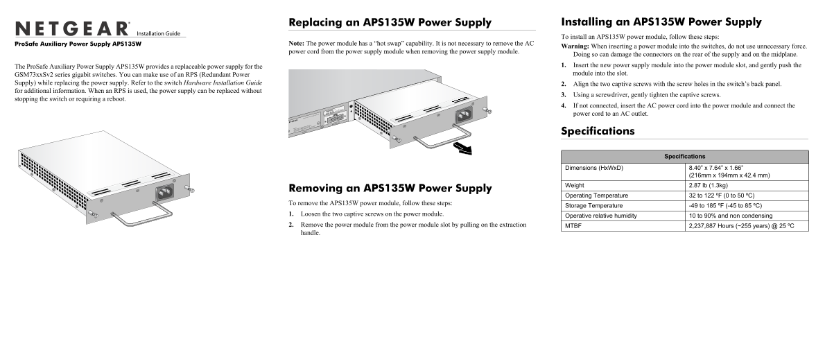
Page 1 Text Content
Replacing an APS135W Power Supply Installing an APS135W Power Supply To install an APS135W power module, follow these steps:
July 2009e Pro Safe Auxiliary Power Supply APS135W
Note: The power module has a “hot swap” capability. It is not necessary to remove the AC
Warning: When inserting a power module into the switches, do not use unnecessary force.
power cord from the power supply module when removing the power supply module.
Doing so can damage the connectors on the rear of the supply and on the midplane. The Pro Safe Auxiliary Power Supply APS135W provides a replaceable power supply for the 1. Insert the new power supply module into the power module slot, and gently push the GSM73xx Sv2 series gigabit switches. You can make use of an RPS (Redundant Power module into the slot.
Supply) while replacing the power supply. Refer to the switch Hardware Installation Guide 2. Align the two captive screws with the screw holes in the switch’s back panel. for additional information. When an RPS is used, the power supply can be replaced without
3. Using a screwdriver, gently tighten the captive screws.
stopping the switch or requiring a reboot.
4. If not connected, insert the AC power cord into the power module and connect the power cord to an AC outlet.
RPS Connector
Specifications
Specifications
Dimensions (Hx Wx D) 8.40” x 7.64” x 1.66”
(216mm x 194mm x 42.4 mm)
Weight 2.87 lb (1.3kg)
Removing an APS135W Power Supply
Operating Temperature 32 to 122 ºF (0 to 50 ºC)
To remove the APS135W power module, follow these steps:
Storage Temperature -49 to 185 ºF (-45 to 85 ºC)
1. Loosen the two captive screws on the power module.
Operative relative humidity 10 to 90% and non condensing
2. Remove the power module from the power module slot by pulling on the extraction MTBF 2,237,887 Hours (~255 years) @ 25 ºC handle.
Page Summary Contents For Netgear APS135W - ProSAFE 135W Auxiliary Power Supply Install Guide
Manual Details
| Brand | NETGEAR |
|---|---|
| Pages | 2 |
| File Size | 176.24 KB |
| Published | June 04, 2026 |
Enter the captcha to get the download link:

Frequently Asked Questions
How do I install an APS135W power module?
Insert the new module, align the two captive screws, gently tighten them, and finally connect the AC power cord.
Is specialized hardware needed to replace the power supply easily?
No, if an RPS (Redundant Power Supply) is used, replacement can occur without stopping the switch or requiring a reboot.
What are the physical dimensions of the APS135W power supply?
It measures 8.40” x 7.64” x 1.66” (216mm x 194mm x 42.4 mm).
How do I safely prepare for or complete the removal of the unit?
First, loosen the two captive screws, then pull the module out by its extraction handle.