Applying Fairchild Power Switch (FPS) FSBH-series to Standby Auxiliary Power Supply
Summary
Optimized application guide for designing high-efficiency Standby Auxiliary Power Supplies (SMPS) using Fairchild’s FSBH power switches. This manual provides engineers with a comprehensive, step-by-step procedure to ensure stable operation across wide AC voltage ranges (90V-264VAC). Learn design considerations for minimizing standby power consumption, selecting input capacitors, and maximizing overall efficiency in demanding offline conversion systems.
Page 1 Text Content
www.fairchildsemi.com
AN-8024 Applying Fairchild Power Switch (FPSTM) FSBH-series to Standby Auxiliary Power Supply
The FSBH-series has built-in synchronized slope
1. Introduction compensation to achieve stable peak-current-mode control.
The proprietary external line compensation ensures constant
The highly integrated FSBH-series consists of an integrated
output power limit over a wide AC input voltage range, from
current mode Pulse Width Modulator (PWM) and an
90VAC to 264VAC and helps optimize the power stage.
avalanche-rugged 700V Sense FET. It is specifically designed for high-performance offline Switch-Mode Power Many protection functions, such as open-loop / overload Supplies (SMPS) with minimal external components. protection (OLP), over-voltage protection (OVP), brownout
protection, and over-temperature protection (OTP); are fully
The integrated PWM controller features include a
integrated into FSBH-series, which improves the SMPS
proprietary green-mode function that provides off-time
reliability without increasing the system cost.
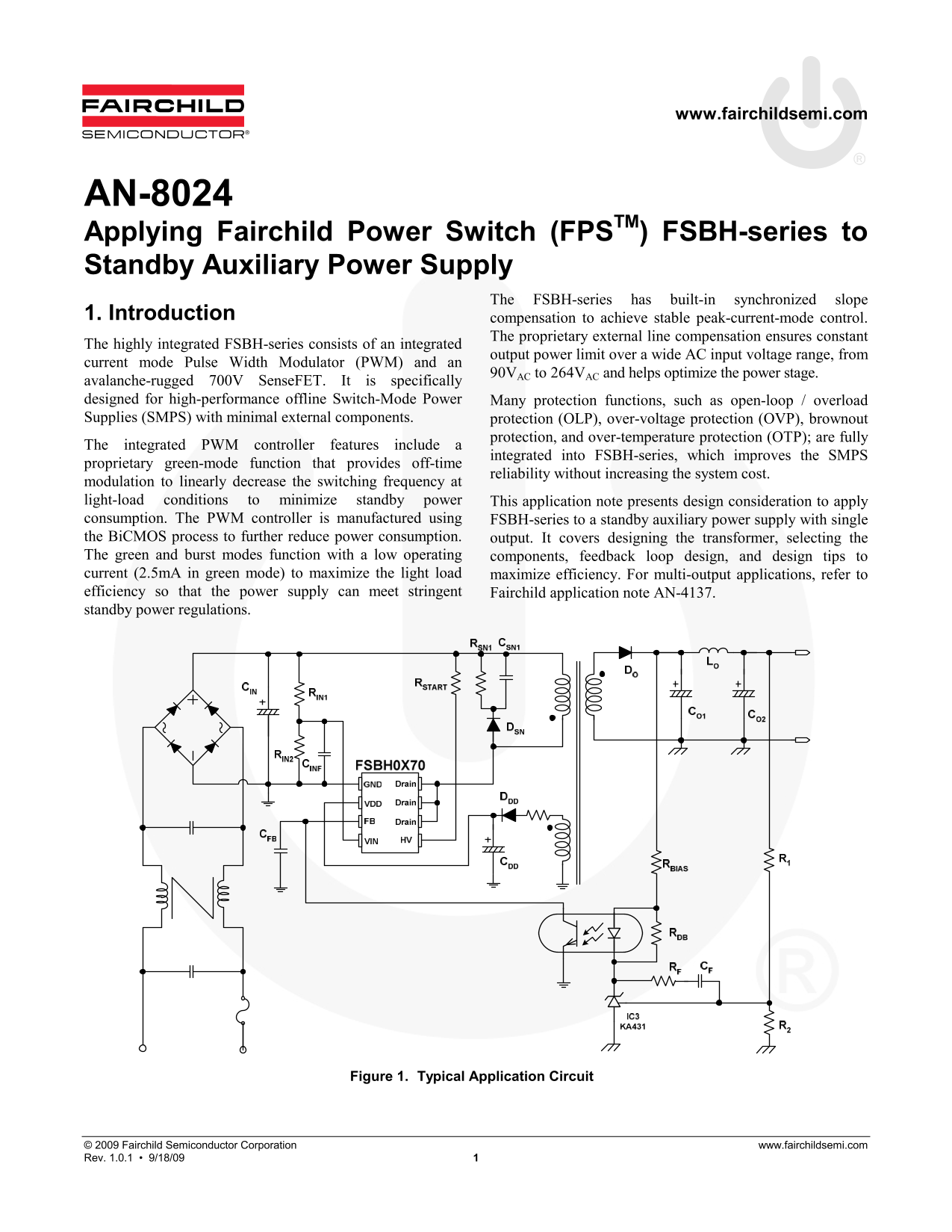
modulation to linearly decrease the switching frequency at light-load conditions to minimize standby power This application note presents design consideration to apply consumption. The PWM controller is manufactured using FSBH-series to a standby auxiliary power supply with single the Bi CMOS process to further reduce power consumption. output. It covers designing the transformer, selecting the The green and burst modes function with a low operating components, feedback loop design, and design tips to current (2.5m A in green mode) to maximize the light load maximize efficiency. For multi-output applications, refer to efficiency so that the power supply can meet stringent Fairchild application note AN-4137. standby power regulations.
Figure 1. Typical Application Circuit
© 2009 Fairchild Semiconductor Corporation www.fairchildsemi.com Rev. 1.0.1 • 9/18/09 1
Page Summary Contents For Applying Fairchild Power Switch (FPS) FSBH-series to Standby Auxiliary Power Supply
Manual Details
| Brand | Fairchild |
|---|---|
| Pages | 10 |
| File Size | 482.65 KB |
| Published | July 15, 2026 |
Enter the captcha to get the download link:
