FAIRCHILD AN-6756 Application Guide for FAN6756 Controlling a Flyback Power Supply with Ultra-Low Standby Power
Summary
FAN6756 is an innovative green-mode PWM controller designed for high efficiency and ultra-low standby power consumption in electronic devices. This application note provides comprehensive design guidance for integrating FAN6756 into flyback switched mode power supplies (SMPS). The manual details a step-by-step engineering process—from estimating input power to determining transformer inductance—ensuring optimal performance with minimal external components. It is essential reading for designers building offline isolated AC/DC power solutions requiring exceptional standby and no-load efficiency.
Page 1 Text Content
AN-6756 Applying FAN6756 to Control a Flyback Power Supply with Ultra-Low Standby Power
discharge methods. At no-load or extremely light-load
1. Introduction
conditions, Standby Mode dramatically reduces the switching
Requirements for low standby power consumption are losses by minimizing the switching frequency while increasing due to the environmental impact of the energy maintaining the controller supply voltage at the minimum wasted by idle electronic devices. Fairchild’s new-generation level. Combined with ultra-low operation current in Standby green-mode PWM controller, FAN6756, incorporates Mode, the power consumption of PWM controller itself is innovative m WSaver™ technology, which dramatically also minimized. reduces the standby and no-load power consumption of a
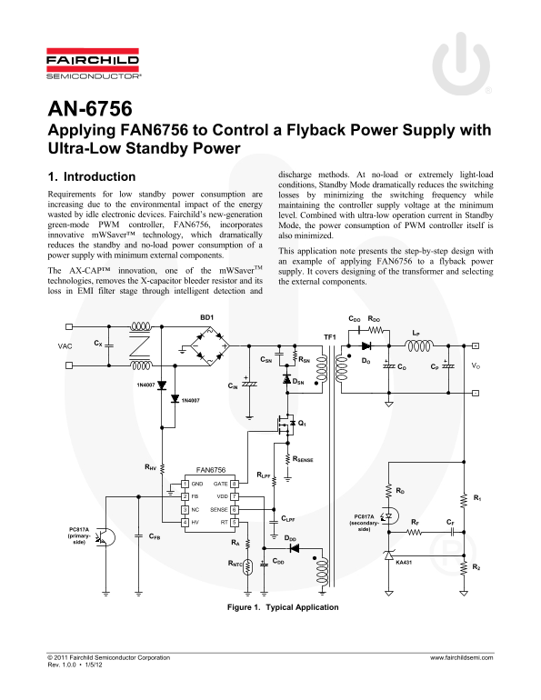
This application note presents the step-by-step design with
power supply with minimum external components.
an example of applying FAN6756 to a flyback power
The AX-CAP™ innovation, one of the m WSaver TM supply. It covers designing of the transformer and selecting technologies, removes the X-capacitor bleeder resistor and its the external components. loss in EMI filter stage through intelligent detection and
BD1 RDOCDO
CSN RSN DO
CO CP VO
1N4007 CIN
RSENSE
FAN6756
GATE 8GND
FB VDD
NC SENSE
PC817A
HV RT (secondary- RF CF
PC817A side)
(primary- CFB
side) RA
CDD KA431
Figure 1. Typical Application
© 2011 Fairchild Semiconductor Corporation www.fairchildsemi.com Rev. 1.0.0 • 1/5/12
Page Summary Contents For FAIRCHILD AN-6756 Application Guide for FAN6756 Controlling a Flyback Power Supply with Ultra-Low Standby Power
Manual Details
| Brand | Fairchild |
|---|---|
| Pages | 13 |
| File Size | 571.34 KB |
| Published | May 19, 2026 |
Enter the captcha to get the download link:

Frequently Asked Questions
How does FAN6756 reduce standby power consumption?
It uses mWSaver™ technology and an innovative AX-CAP™ design to dramatically reduce standby and no-load power consumption.
What is the use of the SENSE resistor in this circuit?
The SENSE resistor handles the ESD discharge path, directing stray capacitance charges from secondary through the transformer auxiliary winding to ground.
How can I ensure proper grounding for optimal performance?
Keep the area enclosed by the signal traces connected to GND2 first. The current then goes through the transformer auxiliary winding and back to the mains via D and C.