Fairchild Design Guidelines for Flyback Converters Using FSQ-Series Fairchild Power Switch (FPS) Data Manual
Summary
This application note provides design guidelines for flyback converters using Fairchild FSQ-series Power Switches. It covers transformer design, output filtering, and component selection to help engineers reduce size and improve efficiency in off-line SMPS applications.
Page 1 Text Content
www.fairchildsemi.com
Application Note AN-4150 Design Guidelines for Flyback Converters Using FSQ-series Fairchild Power Switch (FPS™)
1. Introduction size and weight, while simultaneously increasing efficiency, productivity, and system reliability. The FSQ-series employs
Compared to conventional hard-switched converters with
an advanced control technique that allows converter to
fixed switching frequencies, the quasi-resonant converter
operate with narrow frequency variation, while keeping the
(QRC) topology is a very attractive alternative for power
quasi-resonant operation. When the converter operates in
supply designers. The increasing popularity of the QRC
discontinuous conduction mode (DCM), the controller finds
approach is based on its ability to reduce electromagnetic
the valley of the drain voltage and turns on the MOSFET at
interference (EMI) while increasing power conversion
the minimum drain voltage. Meanwhile, the converter can
efficiency.
operate with fixed frequency when operating in continuous The FSQ-series FPS™ (Fairchild Power Switch) is an conduction mode (CCM), which allows converter design as integrated Pulse Width Modulation (PWM) controller and simple as conventional PWM converters.
Sense FET specifically designed for quasi-resonant off-line
This application note presents practical design consider-
Switch Mode Power Supplies (SMPS) with minimal external
ations of a flyback converter employing the FSQ-series
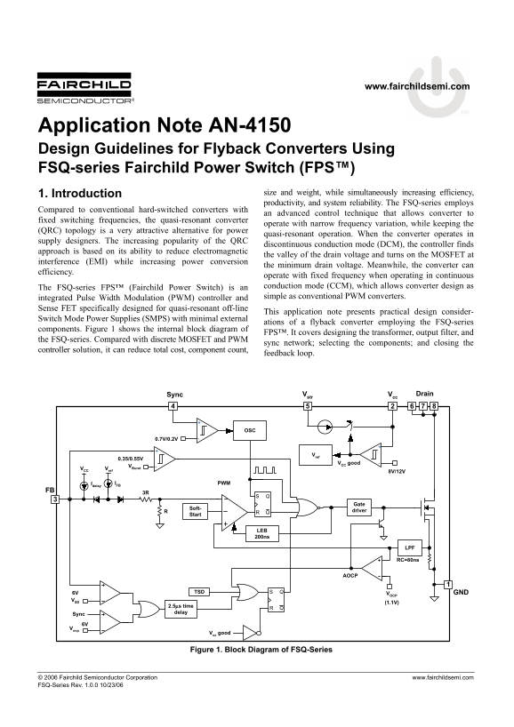
components. Figure 1 shows the internal block diagram of
FPS™. It covers designing the transformer, output filter, and
the FSQ-series. Compared with discrete MOSFET and PWM
sync network; selecting the components; and closing the
controller solution, it can reduce total cost, component count,
feedback loop.
Sync Vstr Vcc Drain
VCC good
VBurst
VCC Vref
Idelay IFB PWM
Soft-
driver
Start
LEB 200ns
RC=80ns
6V TSD VOCP GND
2.5μs time delay
Sync 6V Vovp
Vcc good
Figure 1. Block Diagram of FSQ-Series
© 2006 Fairchild Semiconductor Corporation www.fairchildsemi.com FSQ-Series Rev. 1.0.0 10/23/06
Page Summary Contents For Fairchild Design Guidelines for Flyback Converters Using FSQ-Series Fairchild Power Switch (FPS) Data Manual
Manual Details
| Brand | Fairchild |
|---|---|
| Pages | 16 |
| File Size | 555.23 KB |
| Published | June 16, 2026 |
Enter the captcha to get the download link:

Frequently Asked Questions
What is the main benefit of using a quasi-resonant flyback converter?
It reduces electromagnetic interference (EMI) while increasing power conversion efficiency.
How does the FSQ-series FPS achieve reduced switching loss?
It turns on the MOSFET at the valley (minimum voltage point) of the drain voltage oscillation.
What are the different operating modes of the FSQ-series converter?
It operates in quasi-resonant mode in DCM and at a fixed frequency in CCM.
What components are integrated into the FSQ-series Fairchild Power Switch?
It integrates a PWM controller and a Sense FET.