Netgear GSM7224R - ProSAFE 24-Port Gigabit L2 Managed Switch with Static Routing Installation Guide
Summary
This manual guides IT professionals and network administrators through the comprehensive physical installation and initial setup of the 7000 Series Managed Switch. It covers essential connectivity details, including using various Category cables for robust data transfer. Users will learn how to establish switch management access by connecting a console port—whether assigning a static IP address or utilizing DHCP server capabilities—enabling seamless deployment into complex network environments.
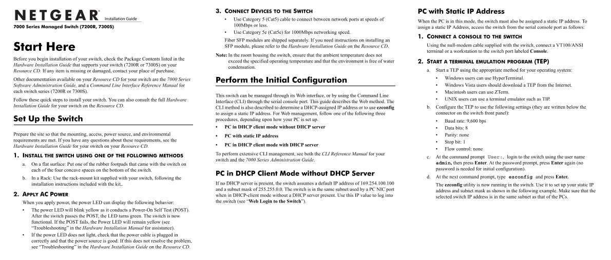
Page 1 Text Content
3. CONNECT DEVICES TO THE SWITCH PC with Static IP Address Use Category 5 (Cat5) cable to connect between network ports at speeds of
When the PC is in this mode, the switch must also be assigned a static IP address. To
100Mbps or less.
7000 Series Managed Switch (7200R, 7300S) assign a static IP Address, access the switch from the serial console port as follows:
Use Category 5e (Cat5e) for 1000Mbps networking speed.
1. CONNECT A CONSOLE TO THE SWITCH
Fiber SFP modules are shipped separately. If you need instructions on installing an
SFP module, please refer to the Hardware Installation Guide on the Resource CD. Using the null-modem cable supplied with the switch, connect a VT100/ANSI
Start Here
terminal or a workstation to the switch port labeled Console.
Note: In the room housing the switch, ensure that the ambient temperature does not
Before you begin installation of your switch, check the Package Contents listed in the
exceed the specified operating temperature and that the environment is free of water 2. START A TERMINAL EMULATION PROGRAM (TEP)
Hardware Installation Guide that supports your switch (7200R or 7300S) on your
condensation.
Resource CD. If any item is missing or damaged, contact your place of purchase. a. Start a TEP using the appropriate method for your operating system: Windows users can use Hyper Terminal.
Other documentation available on your Resource CD for your switch are the 7000 Series Perform the Initial Configuration
Software Administration Guide, and a Command Line Interface Reference Manual for Windows Vista users should download a TEP from the Internet.
each switch series (7200R or 7300S). Macintosh users can use ZTerm.
This switch can be managed through its Web interface, or by using the Command Line
Follow these quick steps to install your switch. You can also consult the full Hardware UNIX users can use a terminal emulator such as TIP.
Interface (CLI) through the serial console port. This guide describes the Web method. The
Installation Guide for your switch on the Resource CD.
CLI method is also described to determine a DHCP-assigned IP address or to use ezconfig b. Configure the TEP to use the following settings (they are written below the to assign a static IP address. For Web management, follow one of the following three connector on the switch front panel):
Set Up the Switch procedures, depending upon how your PC is set up.
Baud rate: 9,600 bps
PC in DHCP client mode without DHCP server Data bits: 8
Prepare the site so that the mounting, access, power source, and environmental Parity: none
PC with static IP address
requirements are met. If you have any questions about these requirements, see the
Stop bit: 1
PC in DHCP client mode with DHCP server
Hardware Installation Guide for your switch on your Resource CD.
Flow control: none
To perform extensive CLI management, see both the CLI Reference Manual for your
1. INSTALL THE SWITCH USING ONE OF THE FOLLOWING METHODS c. At the command prompt User:, login to the switch using the user name
switch and the 7000 Series Administration Guide.
admin, then press Enter. At the password prompt, press Enter again (no
a. On a flat surface: Put one of the rubber footpads that came with the switch on
password is needed for initial configuration).
each of the four concave spaces on the bottom of the switch.
PC in DHCP Client Mode without DHCP Server
d. At the next command prompt, type ezconfig and press Enter.
b. In a Rack: Use the rack-mount kit supplied with your switch, following the
installation instructions included with the kit,. If no DHCP server is present, the switch assumes a default IP address of 169.254.100.100
The ezconfig utility is now running in the switch. Use it to set up your static IP
and a subnet mask of 255.255.0.0. The switch is in the same subnet used by a PC NIC port
address and subnet mask as shown in the following example. Make sure that the
2. APPLY AC POWER when in DHCP-client mode without a DHCP server present. Use this IP value to log into
selected switch IP address is in the same subnet as that of the PCs.
the switch (see “Web Login to the Switch”).
When you apply power, the power LED can display the following behavior: The power LED will blink yellow as it conducts a Power-On Self Test (POST). After the switch passes the POST, the LED turns green. The switch is now functional. If the POST fails, the Power LED will remain yellow (see “Troubleshooting” in the Hardware Installation Manual for assistance). If the power LED does not light, check that the power cable is plugged in correctly and that the power source is good. If this does not resolve the problem, see “Troubleshooting” in the Hardware Installation Guide on the Resource CD.
Page Summary Contents For Netgear GSM7224R - ProSAFE 24-Port Gigabit L2 Managed Switch with Static Routing Installation Guide
Manual Details
| Brand | NETGEAR |
|---|---|
| Pages | 2 |
| File Size | 114.65 KB |
| Published | June 06, 2026 |
Enter the captcha to get the download link:

Frequently Asked Questions
How do I connect my PC for initial switch setup using a static IP?
Connect a VT100/ANSI terminal via the null-modem cable to the Console port, then access it through a Terminal Emulation Program (TEP).
What settings should I use when setting up the TEP for console access?
Use 9,600 bps Baud rate, 8 Data bits, none Parity, 1 Stop bit, and none Flow control.
How do I know if the switch installation was successful after applying power?
The power LED will blink yellow during POST and turn green when the switch is functional. If it remains yellow or does not light, check the power source.