# A B C D E F G H I J K L M N O P Q R S T U V W X Y Z

Motorola MC34023 MC33023 Data Sheet / Manual

Summary

These high-speed pulse width modulator controllers in the MC34023 series are specialized for designing efficient Off-Line and DC-to-DC converter applications. Offering cost-effective performance with minimal external components, the IC integrates a temperature-compensated reference, wide bandwidth error amplifier, and protective features like UVLO and cycle-by-cycle current limiting. This manual provides detailed technical specifications, electrical characteristics, operational parameters, and configuration guides for designers building advanced power control systems.
📄 Preview PAGE OF 19

Page 1 Text Content

查询MC33023供应商

Order this document by MC34023/D

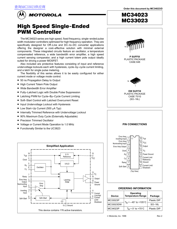
The MC34023 series are high speed, fixed frequency, single–ended pulse width modulator controllers optimized for high frequency operation. They are specifically designed for Off–Line and DC–to–DC converter applications offering the designer a cost–effective solution with minimal external components. These integrated circuits feature an oscillator, a temperature compensated reference, a wide bandwidth error amplifier, a high speed

P SUFFIX

current sensing comparator, and a high current totem pole output ideally

PLASTIC PACKAGE

suited for driving a power MOSFET.

CASE 648

Also included are protective features consisting of input and reference undervoltage lockouts each with hysteresis, cycle–by–cycle current limiting, and a latch for single pulse metering. The flexibility of this series allows it to be easily configured for either current mode or voltage mode control. 50 ns Propagation Delay to Output High Current Totem Pole Output Wide Bandwidth Error Amplifier

DW SUFFIX

Fully–Latched Logic with Double Pulse Suppression

PLASTIC PACKAGE

Latching PWM for Cycle–By–Cycle Current Limiting CASE 751G

(SO–16L)

Soft–Start Control with Latched Overcurrent Reset Input Undervoltage Lockout with Hysteresis Low Start–Up Current (500 µA Typ) Internally Trimmed Reference with Undervoltage Lockout 90% Maximum Duty Cycle (Externally Adjustable) Precision Trimmed Oscillator

Voltage or Current Mode Operation to 1.0 MHz PIN CONNECTIONS

Functionally Similar to the UC3823

Error Amp

Inverting Input Vref

Error Amp

Noninverting Input

Simplified Application Error Amp Output Output

Clock VC

5.1V RT Power Ground

Reference

VCC Current Limit

Clock Reference Ramp Ground

RT Current Limit/

Soft–Start

Oscillator Shutdown

(Top View)

Output

Error Amp Latching Output PWM Power

Error

Noninverting Ground

Input

ORDERING INFORMATION

Inverting Input Current Operating

Limit Ref Device Temperature Range Package Soft–Start Current

Soft–Start

Limit/ MC33023P Plastic DIP Shutdown TA = –40° to +105°C

MC33023DW SO–16L

Ground10

MC34023P TA = 0° to +70°C Plastic DIP

This device contains 176 active transistors.

Motorola, Inc. 1996 Rev 2

1MOTOROLA ANALOG IC DEVICE DATA

Page Summary Contents For Motorola MC34023 MC33023 Data Sheet / Manual

Page 1 查询MC33023供应商 Order this document by MC34023/D The MC34023 series are high speed, fixed frequency, single–ended pulse width modulator controllers optimized for high frequency operation. They are specif...
Page 2 MC34023 MC33023 MAXIMUM RATINGS Rating Symbol Value Unit Power Supply Voltage VCC Output Driver Supply Voltage VC Output Current, Source or Sink (Note 1) IO DC 0.5 Pulsed (0.5 µs) 2.0 Current Sense, S...
Page 3 MC34023 MC33023 ELECTRICAL CHARACTERISTICS (VCC = 15 V, RT = 3.65 kΩ, CT = 1.0 n F, for typical values TA = +25°C, for min/max values TA is the operating ambient temperature range that applies [Note 2...
Page 4 MC34023 MC33023 Figure 1. Timing Resistor versus PE VO LT AG AI (d B) , T IM IN ES IS TO Figure 2. Oscillator Frequency versus Temperature VO L, O Oscillator Frequency VCC = 15 V RT = 1.2 k TA = + 25°...
Page 5 MC34023 MC33023 Figure 7. Reference Voltage Change Figure 8. Reference Short Circuit Current , C EN LI IT IN PU FF SE VO LT AG (m V) ef , R EF ER EN VO LT AG AN (m V) versus Source Current versus Temp...
Page 6 MC34023 MC33023 Figure 13. Soft–Start Charge Current Figure 14. Output Saturation Voltage versus Temperature versus Load Current FT -S TA RT AR EN A) ch g, S Source Saturation VCC = 15 V (Load to Grou...
Page 7 MC34023 MC33023 Figure 18. Representative Block Diagram VCC Vin Vref Reference Regulator VCC VCC UVLO Clock 4.2 V Vref UVLO Oscillator VC RT CT Output Ramp 1.25 V Comparator Power Ground Error Amp Out...
Page 8 MC34023 MC33023 OPERATING DESCRIPTION The MC33023 and MC34023 series are high speed, fixed limiting the duty cycle. The time it takes for a capacitor to frequency, single–ended pulse width modulator c...
Page 9 MC34023 MC33023 Undervoltage Lockout current feedback loop. It has been shown that the instability is There are two undervoltage lockout circuits within the IC. caused by a double pole at half the swi...
Page 10 MC34023 MC33023 PIN FUNCTION DESCRIPTION Pin DIP/SOIC Function Description Error Amp This pin is usually used for feedback from the output of the power supply. Inverting Input Error Amp This pin is us...
Page 11 MC34023 MC33023 Figure 23. Resistive Current Sensing Figure 24. Primary Side Current Sensing ISense ISense The addition of an RC filter will eliminate instability caused by the The addition of an RC f...
Page 12 MC34023 MC33023 Figure 26. Dead Time Addition Figure 27. External Clock Synchronization Oscillator Oscillator RT Additional dead time can be added by the addition of a dead time resistor from Vref to ...
Page 13 MC34023 MC33023 Figure 30. Buffered Maximum Clamp Level Figure 31. Bipolar Transistor Drive VC Vin Base Charge Removal To Current RS12 Sense Input In voltage mode operation, the maximum duty cycle can...
Page 14 MC34023 MC33023 ig re 4. lic at io ir cu it Figure 34. in to ef er en ce 5. 1. eg ul at or 4. VL 9. BR TL sc illa to VL 4. 7IR 0M 1. om pa ra to 0. PW at ch ur re nt Li it Er ro 9. Aµ Sh ut do 0. So f...
Page 15 MC34023 MC33023 Figure 35. PC Board With Components 6.5″ (Top View) 15MOTOROLA ANALOG IC DEVICE DATA
Page 16 MC34023 MC33023 Figure 36. PC Board Without Components (Top View) 6.5″ (Bottom View) MOTOROLA ANALOG IC DEVICE DATA
Page 17 MC34023 MC33023 OUTLINE DIMENSIONS P SUFFIX PLASTIC PACKAGE CASE 648–08 NOTES: 1. DIMENSIONING AND TOLERANCING PER ANSI Y14.5M, 1982. 2. CONTROLLING DIMENSION: INCH. 3. DIMENSION L TO CENTER OF LEADS ...
Page 18 MC34023 MC33023 OUTLINE DIMENSIONS FN SUFFIX PLASTIC PACKAGE CASE 775–02 (PLCC) 0.007 (0.180) –M SM –N– Y BRK 0.007 (0.180) –M SM G1X 0.010 (0.250) –M SS VIEW D–D 0.007 (0.180) –M SM 0.007 (0.180) –M ...
Page 19 MC34023 MC33023 Motorola reserves the right to make changes without further notice to any products herein. Motorola makes no warranty, representation or guarantee regarding the suitability of its prod...

Manual Details

Brand Motorola
Pages 19
File Size 474.72 KB
Published May 29, 2026
57 views

Enter the captcha to get the download link:

captcha

Frequently Asked Questions

What applications are the MC34023 series optimized for?

They are optimized for Off-Line and DC-to-DC converter applications, designed to be cost-effective with minimal external components.

Does the device offer multiple control options?

Yes, it allows easy configuration for either current mode or voltage mode control. It also supports Voltage or Current Mode Operation up to 1.0 MHz.

What protective features are included with this series?

It includes protective features such as input and reference undervoltage lockouts (UVLO) both with hysteresis, cycle-by-cycle current limiting, and a latch for single pulse metering.

What is the operating temperature range for the MC33023?

The MC33023 device operates in the temperature range of –40° to +105°C.