# A B C D E F G H I J K L M N O P Q R S T U V W X Y Z

MOTOROLA LM2576 DATA SHEET

Summary

This high-efficiency monolithic integrated circuit serves as an ideal step-down (buck) switching regulator, simplifying the design of robust power supplies. Capable of fixed or adjustable outputs (3.3V to 15V), it ensures excellent line regulation while minimizing required external components. The accompanying technical manual provides hardware engineers and designers with comprehensive details on operating ratings, absolute maximum limits, typical circuit diagrams, and integration guidelines for reliable power conversion applications.
📄 Preview PAGE OF 28

Page 1 Text Content

Order this document by LM2576/D

EASY SWITCHER

The LM2576 series of regulators are monolithic integrated circuits ideally

3.0 A STEP–DOWN

suited for easy and convenient design of a step–down switching regulator

(buck converter). All circuits of this series are capable of driving a 3.0 A load VOLTAGE REGULATOR

with excellent line and load regulation. These devices are available in fixed

output voltages of 3.3 V, 5.0 V, 12 V, 15 V, and an adjustable output version. SEMICONDUCTOR

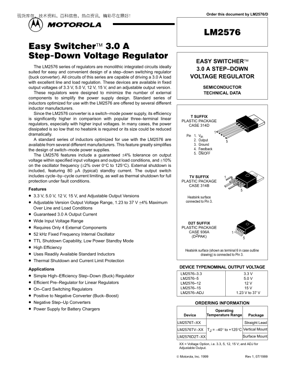
These regulators were designed to minimize the number of external TECHNICAL DATA components to simplify the power supply design. Standard series of inductors optimized for use with the LM2576 are offered by several different inductor manufacturers. Since the LM2576 converter is a switch–mode power supply, its efficiency

T SUFFIX

is significantly higher in comparison with popular three–terminal linear

PLASTIC PACKAGE

regulators, especially with higher input voltages. In many cases, the power

CASE 314D

dissipated is so low that no heatsink is required or its size could be reduced dramatically.

Pin 1. Vin

A standard series of inductors optimized for use with the LM2576 are 2. Output

available from several different manufacturers. This feature greatly simplifies 3. Ground 4. Feedback

the design of switch–mode power supplies.

5. ON/OFF

The LM2576 features include a guaranteed ±4% tolerance on output voltage within specified input voltages and output load conditions, and ±10% on the oscillator frequency (±2% over 0°C to 125°C). External shutdown is included, featuring 80 µA (typical) standby current. The output switch includes cycle–by–cycle current limiting, as well as thermal shutdown for full TV SUFFIX protection under fault conditions. PLASTIC PACKAGE

CASE 314B

Features 3.3 V, 5.0 V, 12 V, 15 V, and Adjustable Output Versions

Heatsink surface connected to Pin 3.

Adjustable Version Output Voltage Range, 1.23 to 37 V ±4% Maximum Over Line and Load Conditions Guaranteed 3.0 A Output Current Wide Input Voltage Range

D2T SUFFIX Requires Only 4 External Components PLASTIC PACKAGE CASE 936A

52 k Hz Fixed Frequency Internal Oscillator

(D2PAK)

TTL Shutdown Capability, Low Power Standby Mode High Efficiency

Heatsink surface (shown as terminal 6 in case outline

Uses Readily Available Standard Inductors drawing) is connected to Pin 3. Thermal Shutdown and Current Limit Protection

DEVICE TYPE/NOMINAL OUTPUT VOLTAGE

Applications

LM2576–3.3 3.3 V

Simple High–Efficiency Step–Down (Buck) Regulator

LM2576–5 5.0 V

Efficient Pre–Regulator for Linear Regulators LM2576–12 12 V

LM2576–15 15 V

On–Card Switching Regulators

LM2576–ADJ 1.23 V to 37 V

Positive to Negative Converter (Buck–Boost) Negative Step–Up Converters ORDERING INFORMATION Power Supply for Battery Chargers

Operating Device Temperature Range Package

LM2576T–XX Straight Lead

LM2576TV–XX TJ = –40° to +125°C Vertical Mount LM2576D2T–XX Surface Mount

XX = Voltage Option, i.e. 3.3, 5, 12, 15 V; and ADJ for Adjustable Output.

Motorola, Inc. 1999 Rev 1, 07/1999

1MOTOROLA ANALOG IC DEVICE DATA

Page Summary Contents For MOTOROLA LM2576 DATA SHEET

Page 1 Order this document by LM2576/D EASY SWITCHER The LM2576 series of regulators are monolithic integrated circuits ideally 3.0 A STEP–DOWN suited for easy and convenient design of a step–down switching...
Page 2 LM2576 Figure 1. Block Diagram and Typical Application Typical Application (Fixed Output Voltage Versions) Feedback 7.0 V – 40 V +Vin L1 LM2576 Unregulated 100 µH Output DC Input 5.0 V Regulated Outpu...
Page 3 LM2576 OPERATING RATINGS (Operating Ratings indicate conditions for which the device is intended to be functional, but do not guarantee specific performance limits. For guaranteed specifications and t...
Page 4 LM2576 DEVICE PARAMETERS ELECTRICAL CHARACTERISTICS (Unless otherwise specified, Vin = 12 V for the 3.3 V, 5.0 V, and Adjustable version, Vin = 25 V for the 12 V version, and Vin = 30 V for the 15 V v...
Page 5 LM2576 TYPICAL PERFORMANCE CHARACTERISTICS (Circuit of Figure 15) , Q IE SC EN EN (m A) IN PU TP IF FE EN TI AL (V TP VO LT AG AN ou t, O Figure 2. Normalized Output Voltage Figure 3. Line Regulation ...
Page 6 LM2576 TYPICAL PERFORMANCE CHARACTERISTICS (Circuit of Figure 15) AL IZ ED EQ EN , S TA BY IE SC EN EN (µ A) st by Figure 8. Standby Quiescent Current Figure 9. Switch Saturation Voltage TJ = 25°C –40...
Page 7 LM2576 TYPICAL PERFORMANCE CHARACTERISTICS (Circuit of Figure 15) Figure 13. Switching Waveforms Figure 14. Load Transient Response 100 m V Output 4.0 A Voltage Change Load 2.0 A 2.0 A Current 1.0 A 1...
Page 8 LM2576 Figure 15. Typical Test Circuit Fixed Output Voltage Versions Feedback LM2576 L1 Fixed Output1 100 µH Output Vout ON/OFFGnd Unregulated DC Input Load MBR360 Cin 100 µF, 75 V, Aluminium Electrol...
Page 9 LM2576 PIN FUNCTION DESCRIPTION Pin Symbol Description (Refer to Figure 1) Vin This pin is the positive input supply for the LM2576 step–down switching regulator. In order to minimize voltage transien...
Page 10 LM2576 Procedure (Fixed Output Voltage Version) In order to simplify the switching regulator design, a step–by–step design procedure and some examples are provided. Procedure Example Given Parameters:...
Page 11 LM2576 Procedure (Fixed Output Voltage Version) (continued)In order to simplify the switching regulator design, a step–by–step design procedure and some examples are provided. Procedure Example 5. Out...
Page 12 LM2576 Procedure (Adjustable Output Version: LM2576–ADJ) (continued) Procedure Example 4. Inductor Selection (L1) 4. Inductor Selection (L1) A. Use the following formula to calculate the inductor Volt...
Page 13 LM2576 LM2576 Series Buck Regulator Design Procedures (continued) AX IM IN PU VO LT AG (V AX IM IN PU VO LT AG (V Indicator Value Selection Guide (For Continuous Mode Operation) Figure 18. LM2576–3.3 ...
Page 14 LM2576 Table 1. Diode Selection Guide Schottky Fast Recovery Through Surface Through Surface Through Surface Through Surface Hole Mount Hole Mount Hole Mount Hole Mount 20 V 1N5820 SK32 1N5823 MBR320P...
Page 15 LM2576 Table 3. Example of Several Inductor Manufacturers Phone/Fax Numbers Phone + 1–619–674–8100 Pulse Engineering, Inc. Fax + 1–619–674–8262 Phone + 353–9324–107 Pulse Engineering, Inc. Europe Fax ...
Page 16 LM2576 because of their fast switching speed and low forward different design load currents are selected. For light loads voltage drop. (less than approximately 300 m A) it may be desirable to They pr...
Page 17 LM2576 Do Not Operate an Inductor Beyond its Figure 24. Discontinuous Mode Switching Current Maximum Rated Current Waveforms Exceeding an inductor’s maximum current rating may cause the inductor to ov...
Page 18 LM2576 Thermal Analysis and Design If the actual operating temperature is greater than the The following procedure must be performed to determine selected safe operating junction temperature, then a l...
Page 19 LM2576 Since the switch currents in this buck–boost configuration Figure 27. Inverting Buck–Boost Regulator are higher than in the standard buck converter topology, the with Delayed start–up available...
Page 20 LM2576 currents require a large value output capacitor (in the range Figure 29. Inverting Buck–Boost Regulator Shutdown of thousands of µF). The recommended range of inductor Circuit Using a PNP Trans...
Page 21 LM2576 predetermined threshold level with respect to the ground Under normal continuous inductor current operating Pin 3, which is determined by the following expression: conditions, the worst case oc...
Page 22 LM2576 THE LM2576–5 STEP–DOWN VOLTAGE REGULATOR WITH 5.0 V @ 3.0 A OUTPUT POWER CAPABILITY. TYPICAL APPLICATION WITH THROUGH–HOLE PC BOARD LAYOUT Figure 35. Schematic Diagram of the LM2576–5 Step–Down...
Page 23 LM2576 THE LM2576–ADJ STEP–DOWN VOLTAGE REGULATOR WITH 8.0 V @ 1.0 A OUTPUT POWER CAPABILITY. TYPICAL APPLICATION WITH THROUGH–HOLE PC BOARD LAYOUT Figure 38. Schematic Diagram of the 8.0 V @ 3.0 A St...
Page 24 LM2576 OUTLINE DIMENSIONS T SUFFIX PLASTIC PACKAGE CASE 314D–03 ISSUE D SEATING PLANE–T– NOTES: 1. DIMENSIONING AND TOLERANCING PER ANSI –Q– Y14.5M, 1982. 2. CONTROLLING DIMENSION: INCH. 3. DIMENSION ...
Page 25 LM2576 OUTLINE DIMENSIONS D2T SUFFIX PLASTIC PACKAGE CASE 936A–02 (D2PAK) ISSUE A NOTES: DIMENSIONING AND TOLERANCING PER ANSI Y14.5M, 1982. –T– TERMINAL 6 CONTROLLING DIMENSION: INCH. OPTIONAL TAB CO...
Page 26 LM2576 NOTES MOTOROLA ANALOG IC DEVICE DATA
Page 27 LM2576 Motorola reserves the right to make changes without further notice to any products herein. Motorola makes no warranty, representation or guarantee regarding the suitability of its products for ...
Page 28 LM2576 Mfax is a trademark of Motorola, Inc. How to reach us: USA/EUROPE/Locations Not Listed: Motorola Literature Distribution; JAPAN: Nippon Motorola Ltd.: SPD, Strategic Planning Office, 4–32–1, P....

Manual Details

Brand Motorola
Pages 28
File Size 304.63 KB
Published May 27, 2026
98 views

Enter the captcha to get the download link:

captcha

Frequently Asked Questions

What is the output voltage range for adjustable versions?

The adjustable version supports an output voltage range of 1.23 V to 37 V ±4%.

How much current can the LM2576 regulators guarantee?

They are guaranteed to provide a 3.0 A output current.

Does the device require an external heatsink?

No, for both Case 314B and 314D, the product's dissipation is low enough that no heatsink is required or it can be significantly reduced.

What safety features are included by default?

Features include cycle–by–cycle current limiting and thermal shutdown protection under fault conditions.