LINEAR AN97-1 Data Handbook
Summary
This application note provides detailed instructions for accurately characterizing the linearity performance of low-distortion IC components, specifically focusing on third-order intermodulation products (IM3) using the LT5514. It guides engineers and technical professionals through setting up specialized test equipment, including signal generators and spectrum analyzers, to evaluate the component's maximum resolution and intrinsic distortion. The manual covers complex two-tone testing procedures required for reliable IC performance measurement and optimization of the test setup itself.
Page 1 Text Content
Application Note 97
January 2006
Accurate Measurement of LT5514 Third Order Intermodulation Products Dorin Seremeta
INTRODUCTION for the maximum resolution achievable with the available test equipment.
Accurate measurement of the third order intercept point
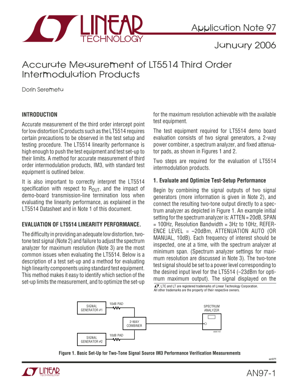
for low distortion IC products such as the LT5514 requires The test equipment required for LT5514 demo board certain precautions to be observed in the test setup and evaluation consists of two signal generators, a 2-way testing procedure. The LT5514 linearity performance is power combiner, a spectrum analyzer, and fixed attenua- high enough to push the test equipment and test set-up to tor pads, as shown in Figures 1 and 2.
their limits. A method for accurate measurement of third
Two steps are required for the evaluation of LT5514
order intermodulation products, IM3, with standard test
intermodulation products.
equipment is outlined below.
It is also important to correctly interpret the LT5514 1. Evaluate and Optimize Test-Setup Performance
specification with respect to ROUT, and the impact of
Begin by combining the signal outputs of two signal
demo-board transmission-line termination loss when
generators (more information is given in Note 2), and
evaluating the linearity performance, as explained in the
connect the resulting two-tone output directly to a spec-
LT5514 Datasheet and in Note 1 of this document.
trum analyzer as depicted in Figure 1. An example initial setting for the spectrum analyzer is: ATTEN = 20d B, SPAN EVALUATION OF LT5514 LINEARITY PERFORMANCE. = 100Hz, Resolution Bandwidth = 3Hz to 10Hz, REFER- ENCE LEVEL = –20d Bm, ATTENUATION AUTO (OR
The difficulty in providing an adequate low distortion, two-
MANUAL, 10d B). Each frequency of interest should be
tone test signal (Note 2) and failure to adjust the spectrum
inspected, one at a time, with the spectrum analyzer at
analyzer for maximum resolution (Note 3) are the most
minimum span. (Spectrum analyzer settings for maxi-
common issues when evaluating the LT5514. Below is a
mum resolution are discussed in Note 3). The two-tone
description of a test set-up and a method for evaluating
test signal should be set to a power level corresponding to
high linearity components using standard test equipment.
the desired input level for the LT5514 (–23d Bm for opti-
This method makes it easy to identify which section of the
mum maximum output). The signal displayed on the
set-up limits the measurement, and to optimize the set-up
, LTC and LT are registered trademarks of Linear Technology Corporation. All other trademarks are the property of their respective owners.
10d B PAD
SIGNAL SPECTRUM GENERATOR #1 ANALYZER
2-WAY COMBINER
AN97 F01
10d B PAD
SIGNAL GENERATOR #2
Figure 1. Basic Set-Up for Two-Tone Signal Source IM3 Performance Verification Measurements
an97f
AN97-1
Page Summary Contents For LINEAR AN97-1 Data Handbook
Manual Details
| Brand | Linear |
|---|---|
| Pages | 8 |
| File Size | 93.66 KB |
| Published | June 01, 2026 |
Enter the captcha to get the download link:

Frequently Asked Questions
What test equipment is required for measuring LT5514 intermodulation products?
A two-tone test setup requires two signal generators, a power combiner, a spectrum analyzer, and fixed attenuator pads.
When should I check if the OIP3 correction factor applies?
The OIP3 correction factor is valid only when the two-tone source quality is limiting; it does not apply if the Spectrum Analyzer limits Step 1 readings.
What steps are needed to evaluate the LT5514 linearity performance accurately?
A two-way testing procedure must be used: first, evaluate 'Source Only' (Step 1), and second, test the device under test (Step 2).