LINEAR AN119B-1 Data Handbook/Manual
Summary
Optimize your high-density power solutions with compact DC/DC μModule regulators for superior performance and thermal efficiency. This comprehensive guide details the design, implementation, and advanced thermal management of parallel regulator arrays. Learn how to achieve low-profile, powerful power distribution (up to 60W) by utilizing space-saving components and optimizing PCB airflow. Perfect for electrical engineers designing compute boards requiring robust cooling while minimizing footprint size.
Page 1 Text Content
Application Note 119B
April 2008
Powering Complex FPGA-Based Systems Using Highly Integrated DC/DC µModule Regulator Systems Part 2 of 2 Thermal Performance and Layout Alan Chern and Afshin Odabaee
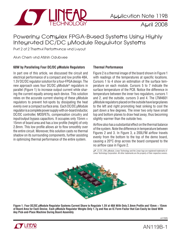
60W by Paralleling Four DC/DC μModule Regulators Thermal Performance In part one of this article, we discussed the circuit and Figure 2 is a thermal image of the board shown in Figure 1 electrical performance of a compact and low profi le 48A, with readings of the temperatures at specifi c locations. 1.5V DC/DC regulator solution for a four-FPGA design. The Cursors 1 to 4 show an estimation of the surface tem- new approach uses four DC/DC μModule® regulators in perature on each module. Cursors 5 to 7 indicate the parallel (Figure 1) to increase output current while shar- surface temperature of the PCB. Notice the difference in ing the current equally among each device. This solution temperature between the inner two regulators, cursors 1 relies on the accurate current sharing of these μModule and 2, and the outside, cursors 3 and 4. The LTM4601 regulators to prevent hot-spots by dissipating the heat μModule regulators placed on the outside have large planes evenly over a compact surface area. Each DC/DC μModule to the left and right promoting heat sinking to cool the regulator is a complete power supply with on-board inductor, part down a few degrees. The inner two only have small DC/DC controller, MOSFETs, compensation circuitry and top and bottom planes to draw heat away, thus becoming input/output bypass capacitors. It occupies only 15mm × slightly warmer than the outside two. 15mm of board area and has a low profi le (height) of only
Airfl ow also has a substantial effect on the thermal balance
2.8mm. This low profi le allows air to fl ow smoothly over
of the system. Note the difference in temperature between
the entire circuit. Moreover, this solution casts no thermal
Figures 2 and 3. In Figure 3, a 200LFM airfl ow travels
shadow on its surrounding components, further assisting
evenly from the bottom to the top of the demo board,
in optimizing thermal performance of the entire system.
causing a 20°C drop across the board compared to the no airfl ow case in Figure 2. L, LT, LTC, LTM, μModule, Linear Technology and the Linear logo are registered trademarks of Linear Technology Corporation. All other trademarks are the property of their respective owners.
Figure 1. Four DC/DC μModule Regulator Systems Current Share to Regulate 1.5V at 48A With Only 2.8mm Profi le and 15mm × 15mm of Board Area for Each Device. Each μModule Regulator Weighs Only 1.7g and Has an IC Form-Factor that Can Easily be Used With Any Pick-and-Place Machine During Board Assembly
an119bfb
AN119B-1
Page Summary Contents For LINEAR AN119B-1 Data Handbook/Manual
Manual Details
| Brand | Linear |
|---|---|
| Pages | 4 |
| File Size | 283.21 KB |
| Published | June 06, 2026 |
Enter the captcha to get the download link:

Frequently Asked Questions
How does the LTM4601 ease thermal management?
Its LGA package and solid attachment to the PCB, combined with power/ground planes, enhance heat sinking.
What is best for achieving optimized system cooling?
A high volume airflow (like 200LFM) moving across the board bottom-to-top helps optimize thermal performance.
Are parallel μModule regulators easy to implement in terms of routing?
Yes, laying out multiple μModules is simple because they utilize a unique LGA package footprint and provide clear power/ground planes.