LINEAR AN78-1 Data Manual
Summary
Optimize your precision measurements with this comprehensive guide for the LTC2400 24-Bit $\Delta\Sigma$ ADC. The application note features a collection of six high-accuracy circuits designed to condition differential input signals to single-ended outputs. It offers tailored solutions for engineers implementing advanced instrumentation, such as digital multimeters or specialized data acquisition systems. Models provide optimized conversion techniques for bipolar and unipolar inputs across diverse supply voltages, ensuring maximized resolution and minimal noise in complex real-world applications.
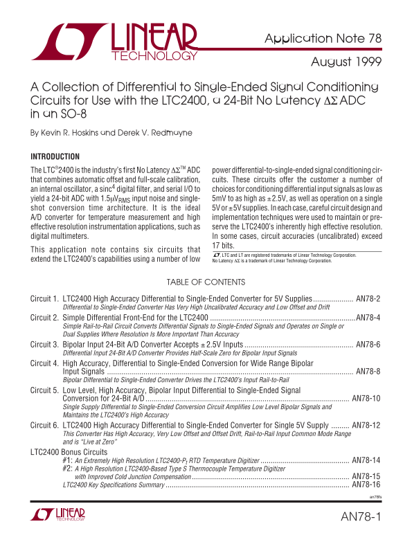
Page 1 Text Content
Application Note 78 August 1999
A Collection of Differential to Single-Ended Signal Conditioning Circuits for Use with the LTC2400, a 24-Bit No Latency ∆Σ ADC in an SO-8 By Kevin R. Hoskins and Derek V. Redmayne
INTRODUCTION The LTC®2400 is the industry’s first No Latency ∆ΣTM ADC power differential-to-single-ended signal conditioning cir- that combines automatic offset and full-scale calibration, cuits. These circuits offer the customer a number of an internal oscillator, a sinc4 digital filter, and serial I/O to choices for conditioning differential input signals as low as yield a 24-bit ADC with 1.5µVRMS input noise and single- 5m V to as high as ±2.5V, as well as operation on a single shot conversion time architecture. It is the ideal 5V or ±5V supplies. In each case, careful circuit design and A/D converter for temperature measurement and high implementation techniques were used to maintain or pre- effective resolution instrumentation applications, such as serve the LTC2400’s inherently high effective resolution. digital multimeters. In some cases, circuit accuracies (uncalibrated) exceed
17 bits.
This application note contains six circuits that
, LTC and LT are registered trademarks of Linear Technology Corporation.
extend the LTC2400’s capabilities using a number of low No Latency ∆Σ is a trademark of Linear Technology Corporation.
TABLE OF CONTENTS
Circuit 1. LTC2400 High Accuracy Differential to Single-Ended Converter for 5V Supplies.................... AN78-2
Differential to Single-Ended Converter Has Very High Uncalibrated Accuracy and Low Offset and Drift
Circuit 2. Simple Differential Front-End for the LTC2400 ........................................................................AN78-4
Simple Rail-to-Rail Circuit Converts Differential Signals to Single-Ended Signals and Operates on Single or Dual Supplies Where Resolution Is More Important Than Accuracy
Circuit 3. Bipolar Input 24-Bit A/D Converter Accepts ± 2.5V Inputs AN78-6
Differential Input 24-Bit A/D Converter Provides Half-Scale Zero for Bipolar Input Signals
Circuit 4. High Accuracy, Differential to Single-Ended Conversion for Wide Range Bipolar
Input Signals AN78-8 Bipolar Differential to Single-Ended Converter Drives the LTC2400’s Input Rail-to-Rail
Circuit 5. Low Level, High Accuracy, Bipolar Input Differential to Single-Ended Signal
Conversion for 24-Bit A/D AN78-10 Single Supply Differential to Single-Ended Conversion Circuit Amplifies Low Level Bipolar Signals and Maintains the LTC2400’s High Accuracy
Circuit 6. LTC2400 High Accuracy Differential to Single-Ended Converter for Single 5V Supply AN78-12
This Converter Has High Accuracy, Very Low Offset and Offset Drift, Rail-to-Rail Input Common Mode Range and is “Live at Zero”
LTC2400 Bonus Circuits
#1: An Extremely High Resolution LTC2400-Pt RTD Temperature Digitizer AN78-14 #2: A High Resolution LTC2400-Based Type S Thermocouple Temperature Digitizer with Improved Cold Junction Compensation AN78-15 LTC2400 Key Specifications Summary AN78-16
an78fs
AN78-1
Page Summary Contents For LINEAR AN78-1 Data Manual
Manual Details
| Brand | Linear |
|---|---|
| Pages | 16 |
| File Size | 173.05 KB |
| Published | June 21, 2026 |
Enter the captcha to get the download link:

Frequently Asked Questions
What is the effective resolution of the LTC2400?
The ADC can maintain an inherently high effective resolution, with some uncalibrated circuit accuracies exceeding 17 bits.
What input voltages can the LTC2400 handle?
It supports a wide range, accepting differential inputs from as low as 5mV to as high as ±2.5V.
How is the LTC2400's noise output specified?
The typical output noise for the LTC2400 is 1.5µV RMS.
Does the LTC2400 have different operating modes?
It supports a 'Live at Zero' mode with an input voltage range of –2 V to +2 V, making it suitable for various conditions.