# A B C D E F G H I J K L M N O P Q R S T U V W X Y Z

LINEAR AN106-1 Data Sheet

Summary

Monitor AC line voltage accurately with the LTC high-performance RMS-to-DC converter family. This module provides an isolated, precise measurement of both standard and distorted waveforms, ensuring reliable power monitoring regardless of input changes or spectral noise. The technical documentation details sigma-$\delta$ conversion techniques, component pinouts, and implementation best practices. It is essential reading for electrical engineers designing circuits that require high accuracy and wide-bandwidth AC voltage sensing.
📄 Preview PAGE OF 20

Page 1 Text Content

Application Note 106 February 2007

Instrumentation Circuitry Using RMS-to-DC Converters RMS Converters Rectify Average Results Jim Williams

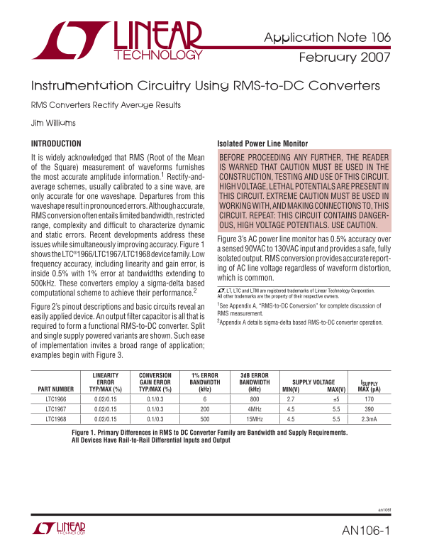
INTRODUCTION Isolated Power Line Monitor It is widely acknowledged that RMS (Root of the Mean BEFORE PROCEEDING ANY FURTHER, THE READER of the Square) measurement of waveforms furnishes IS WARNED THAT CAUTION MUST BE USED IN THE the most accurate amplitude information.1 Rectify-and- CONSTRUCTION, TESTING AND USE OF THIS CIRCUIT. average schemes, usually calibrated to a sine wave, are HIGH VOLTAGE, LETHAL POTENTIALS ARE PRESENT IN only accurate for one waveshape. Departures from this THIS CIRCUIT. EXTREME CAUTION MUST BE USED IN waveshape result in pronounced errors. Although accurate, WORKING WITH, AND MAKING CONNECTIONS TO, THIS RMS conversion often entails limited bandwidth, restricted CIRCUIT. REPEAT: THIS CIRCUIT CONTAINS DANGER- range, complexity and diffi cult to characterize dynamic OUS, HIGH VOLTAGE POTENTIALS. USE CAUTION. and static errors. Recent developments address these

Figure 3’s AC power line monitor has 0.5% accuracy over

issues while simultaneously improving accuracy. Figure 1

a sensed 90VAC to 130VAC input and provides a safe, fully

shows the LTC®1966/LTC1967/LTC1968 device family. Low

isolated output. RMS conversion provides accurate report-

frequency accuracy, including linearity and gain error, is

ing of AC line voltage regardless of waveform distortion,

inside 0.5% with 1% error at bandwidths extending to

which is common.

500k Hz. These converters employ a sigma-delta based

, LT, LTC and LTM are registered trademarks of Linear Technology Corporation.

computational scheme to achieve their performance.2

All other trademarks are the property of their respective owners. 1See Appendix A, “RMS-to-DC Conversion” for complete discussion of

Figure 2’s pinout descriptions and basic circuits reveal an

RMS measurement.

easily applied device. An output fi lter capacitor is all that is

2Appendix A details sigma-delta based RMS-to-DC converter operation.

required to form a functional RMS-to-DC converter. Split and single supply powered variants are shown. Such ease of implementation invites a broad range of application; examples begin with Figure 3.

LINEARITY CONVERSION 1% ERROR 3d B ERROR ERROR GAIN ERROR BANDWIDTH BANDWIDTH SUPPLY VOLTAGE ISUPPLY

PART NUMBER TYP/MAX (%) TYP/MAX (%) (k Hz) (k Hz) MAX(V) MAX (µA)MIN(V)

LTC1966 0.02/0.15 0.1/0.3 2.7 ±5 LTC1967 0.02/0.15 0.1/0.3 4MHz 4.5 5.5 LTC1968 0.02/0.15 0.1/0.3 15MHz 4.5 5.5 2.3m A

Figure 1. Primary Differences in RMS to DC Converter Family are Bandwidth and Supply Requirements. All Devices Have Rail-to-Rail Differential Inputs and Output

an106f

AN106-1

Page Summary Contents For LINEAR AN106-1 Data Sheet

Page 1 Application Note 106 February 2007 Instrumentation Circuitry Using RMS-to-DC Converters RMS Converters Rectify Average Results Jim Williams INTRODUCTION Isolated Power Line Monitor It is widely acknow...
Page 2 Application Note 106 POSITIVE SUPPLY 2.7V TO 5.5V DEPENDING ON DEVICE CHOICE DIFFERENTIAL OUTPUT TO FILTER CAPACITOR INPUTS. INPUT 1 OUTPUT OUTPUT LTC1966 MAX COMMON MODE LTC1967 RANGE = ±V SUPPLY. OU...
Page 3 Application Note 106 RM OU TP UT EA DI NG RR OR The AC line voltage is divided down by T1’s ratio. An isolated Fully Isolated 2500V Breakdown, and reduced potential appears across T1’s secondary B, Wi...
Page 4 Application Note 106 Figure 7 provides isolated power and data output paths to an RMS-to-DC converter, permitting safe, wideband, digital output RMS measurement. A pulse generator confi gured A = 100V...
Page 5 Application Note 106 Low Distortion AC Line RMS Voltage Regulator Almost all AC line voltage regulators rely on some form of waveform chopping, clipping or interruption to function. NOTE: BEFORE PROCE...
Page 6 Application Note 106 The AC line voltage is applied to the Q2-diode bridge. The legitimate input. More subtly, the preamplifi er must have Q2-diode bridge output is sensed by a calibrated variable far...
Page 7 Application Note 106 INPUT HIGH FREQUENCY PATH AC/DC SUMMATION RMS CONVERTER 0m V TO 1m V 1µF LT1122 +V –V OUTPUT IN1 OUT 0V TO 1V 10k* LT1222 LTC1966 OUT RTNIN2 LT107710k* EN GND AN106 F09 LOW FREQUE...
Page 8 Application Note 106 Figure 11 shows preamplifi er response to a 1m V input circuit output, in accordance with the table in the fi gure. step at a gain of X1000. A2’s output is singularly clean, Conti...
Page 9 Application Note 106 current while introducing minimal parasitic loading (see AC Voltage Standard with Stable Frequency and Low Figure 14). The probe’s 50Ω termination allows direct Distortion connect...
Page 10 Application Note 106 4k Hz OUTPUT 1.414VRMS CRYSTAL BRIDGE BRIDGE AMPLIFIER LT1009 2.5V 100k* 10µF 47k RMS-TO-DC CONVERTER 4k Hz 39k JCUT LT1792 LT1010 430p F DISTORTION V+ LT1077 TRIM IN1 OUT LT1006 ...
Page 11 Application Note 106 FILTER NOISE DIODE NOISE DIODE 1µF 10µF PREAMP 1k Hz 15V 0.1µF 160Ω 10k Hz 1µF 1k NC103 –3d B LT1220 0.01µF 100k Hz 7VDC TO 10VDC 0.002µF 500k Hz +NOISE RMS AMPLITUDE 500k Hz FLAT...
Page 12 Application Note 106 2V/DIV FREQUENCY (k Hz) AN106 F19 Figure 19. Amplitude vs Frequency for the Random Noise AN106 F18 5ms/DIV Generator is Essentially Flat to 500k Hz. NC103 Diode Contributes Even N...
Page 13 Application Note 106 in input amplitude while maintaining waveshape. Desired would not be processable. Similar considerations apply to output level is settable with the indicated potentiometer or Figu...
Page 14 Application Note 106 APPENDIX A The last two entries of Table A1 are chopped sine waves as is commonly created with thyristors such as SCRs and Triacs. Figure A2a shows a typical circuit and Figure A2...
Page 15 Application Note 106 How an RMS-to-DC Converter Works How the LTC1966/LTC1967/LTC1968 RMS-to-DC Converters Work Monolithic RMS-to-DC converters use an implicit compu- tation to calculate the RMS value...
Page 16 Application Note 106 Linearity of an RMS-to-DC Converter But the input nonlinearity will still cause problems in an RMS-to-DC converter because it will corrupt the ac- Linearity may seem like an odd p...
Page 17 Application Note 106 APPENDIX B Layout is critical. The most prevalent parasitic in AC measurement is stray capacitance. Keep signal path AC Measurement and Signal Handling Practice connections short ...
Page 18 Application Note 106 Active components, such as amplifi ers, must be treated have tolerances that can corrupt a 1% amplitude accuracy as potential error sources. In particular, as stated in the measur...
Page 19 Application Note 106 The ENR expresses how many times the effective noise When amplifying noise it is important to remember that power delivered to a non-emitting, nonrefl ecting load the noise voltag...
Page 20 Application Note 106 an106f LT 0207 • PRINTED IN USA Linear Technology Corporation AN106-20 1630 Mc Carthy Blvd., Milpitas, CA 95035-7417 (408) 432-1900 ● FAX: (408) 434-0507 ● www.linear.com © LINEAR...

Manual Details

Brand Linear
Pages 20
File Size 345.55 KB
Published May 30, 2026
72 views

Enter the captcha to get the download link:

captcha

Frequently Asked Questions

What safety precautions must be used when working with this circuit?

Caution must be used because high voltage, lethal potentials are present in the construction, testing, and use of this circuit.

How accurate is the isolated power line monitor (Figure 3)?

It has 0.5% accuracy over a signal input range of 90VAC to 130VAC.

Are these converters accurate for varied AC waveforms?

Yes, RMS conversion provides accurate reporting regardless of waveform distortion or complex issues while improving accuracy.

What is the minimum requirement needed to build an RMS-to-DC converter?

An output filter capacitor is all that is required to form a functional RMS-to-DC converter.