# A B C D E F G H I J K L M N O P Q R S T U V W X Y Z

LINEAR LTC1922-1 Data Sheet

Summary

The LTC1922-1 is a high-performance, full-bridge power controller designed for developing isolated, high-efficiency, zero voltage switched (ZVS) power supplies. It integrates synchronous rectification with fixed frequency operation and features robust protection mechanisms suitable for critical systems. This manual provides comprehensive electrical characteristics, operational guidelines, and application details for implementing complex distributed power architectures in fields like telecommunications, infrastructure, and server power solutions.
📄 Preview PAGE OF 24

Page 1 Text Content

查询LTC1922EG-1供应商

LTC1922-1

Synchronous Phase

Modulated Full-Bridge Controller

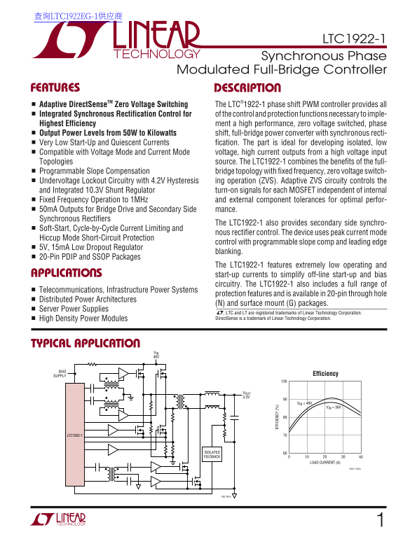
FEATURES DESCRIPTIO Adaptive Direct Sense TM Zero Voltage Switching The LTC®1922-1 phase shift PWM controller provides all Integrated Synchronous Rectification Control for of the control and protection functions necessary to imple- Highest Efficiency ment a high performance, zero voltage switched, phase Output Power Levels from 50W to Kilowatts shift, full-bridge power converter with synchronous recti-

Very Low Start-Up and Quiescent Currents fication. The part is ideal for developing isolated, low Compatible with Voltage Mode and Current Mode voltage, high current outputs from a high voltage input Topologies source. The LTC1922-1 combines the benefits of the full- Programmable Slope Compensation bridge topology with fixed frequency, zero voltage switch- Undervoltage Lockout Circuitry with 4.2V Hysteresis ing operation (ZVS). Adaptive ZVS circuity controls the and Integrated 10.3V Shunt Regulator turn-on signals for each MOSFET independent of internal Fixed Frequency Operation to 1MHz and external component tolerances for optimal perfor- 50m A Outputs for Bridge Drive and Secondary Side mance.

Synchronous Rectifiers

The LTC1922-1 also provides secondary side synchro-

Soft-Start, Cycle-by-Cycle Current Limiting and

nous rectifier control. The device uses peak current mode

Hiccup Mode Short-Circuit Protection

control with programmable slope comp and leading edge

5V, 15m A Low Dropout Regulator

blanking.

20-Pin PDIP and SSOP Packages

The LTC1922-1 features extremely low operating and

APPLICATIO S EF FI CI EN CY start-up currents to simplify off-line start-up and bias

circuitry. The LTC1922-1 also includes a full range of

Telecommunications, Infrastructure Power Systems

protection features and is available in 20-pin through hole

Distributed Power Architectures

(N) and surface mount (G) packages.

Server Power Supplies

, LTC and LT are registered trademarks of Linear Technology Corporation. High Density Power Modules Direct Sense is a trademark of Linear Technology Corporation.

TYPICAL APPLICATIO

VIN 48V

SUPPLY Efficiency

VOUT 3.3V

VIN = 48V

VIN = 36V

LTC1922-1

ISOLATED FEEDBACK

LOAD CURRENT (A)

1922 • TA01b

1922 TA01a

Page Summary Contents For LINEAR LTC1922-1 Data Sheet

Page 1 查询LTC1922EG-1供应商 LTC1922-1 Synchronous Phase Modulated Full-Bridge Controller FEATURES DESCRIPTIO Adaptive Direct Sense TM Zero Voltage Switching The LTC®1922-1 phase shift PWM controller provides all...
Page 2 LTC1922-1 ABSOLUTE AXI RATI GS PACKAGE/ORDER I FOR ATIO (Note 1) TOP VIEW ORDER PART VCC to GND SYNC CT NUMBER Low Impedance Source –0.3V to 10V RAMP GND (Chip Self Regulates at 10.3V) CS OUTA LTC1922...
Page 3 LTC1922-1 ELECTRICAL CHARACTERISTICS The ● denotes the specifications which apply over the full operating temperature range, otherwise specifications are at VCC = 9.5V, CT = 180p F, TA = TMIN to TMAX ...
Page 4 LTC1922-1 TYPICAL PERFOR A CE CHARACTERISTICS EF (V BL AN TI (n s) Oscillator Frequency vs Start-Up ICC vs VCC VCC vs ISHUNT Temperature 10.50 TA = 25°C TA = 25°C CT = 180p F –40–60 –20 VCC (V) ISHUNT...
Page 5 LTC1922-1 TYPICAL PERFOR A CE CHARACTERISTICS FB OL TA GE (V SH UN VO LT AG (V Delay Hysteresis Current vs Start-Up ICC vs Temperature Temperature Slope Current vs Temperature 1.278 SBUS = 1.5V 1.276 ...
Page 6 LTC1922-1 PIN FUNCTIONS SYNC (Pin 1): Synchronization Input/Output for the VREF (Pin 11): 5V Reference Output. VREF is capable of Oscillator. Terminate SYNC with a 5.1k resistor to GND. supplying up t...
Page 7 LTC1922-1 BLOCK DIAGRA VCC VREF CT SYNC SBUS UVLO 5V SHUNT REG REF AND LDO OSC 10.25V “ON” 6V “0FF” ERROR AMPLIFIER 1.2V PHASE MODULATOR OUTA PASSIVE DELAY QB OUTB RAMP BLANK QB OUTE SYNC VREF RECTIFI...
Page 8 LTC1922-1 OPERATIO Phase Shift Full-Bridge PWM 5) Optimized current mode control architecture. Conventional full-bridge switching power supply topolo- Benefit: eliminates glue circuitry, less overshoo...
Page 9 LTC1922-1 OPERATIO Each full cycle of the transformer has two distinct periods risen to VIN, MOSFET MC is switched on by the LTC1922- in which power is delivered to the output, and two “free- 1 Direct...
Page 10 LTC1922-1 OPERATIO .and must be considered when specifying the power trans- State 4 (Power Pulse 2) former. If ZVS is required over the entire range of loads, a During power pulse 2, current builds up...
Page 11 LTC1922-1 OPERATIO Zero Voltage Switching (ZVS) Adaptive Mode A lossless switching transition requires that the respective The LTC1922-1 is configured for adaptive delay sensing full-bridge MOSFETs be...
Page 12 LTC1922-1 OPERATIO PDLY corresponding to several volts across the MOSFET, to VCC as well as signaling that the chip’s bias voltage is the LTC1922-1 can “anticipate” a zero voltage VDS and sufficient t...
Page 13 LTC1922-1 OPERATIO Off-Line Bias Supply Generation generate a voltage as the output is first starting up, or during short-circuit conditions. If a regulated bias supply is not available to provide VCC...
Page 14 LTC1922-1 OPERATIO 2. The LTC1922-1 can either synchronize other PWMs, or (33µA/V(CT)). Thus, at the peak of CT, this current is be synchronized to an external frequency source or PWM approximately 12...
Page 15 LTC1922-1 OPERATIO H = SHUTDOWN UVLO OUTPUTS LATCH PULSE BY PULSE ENABLE CURRENT LIMIT LOGIC CS 400m V OVERLOAD CURRENT LIMIT ENABLE CSS Figure 8. Current Sense/Fault Circuitry Detail The pulse-by-pul...
Page 16 LTC1922-1 OPERATIO PO ER OS (W include, higher cost and complexity, lower accuracy, core RS = 0.025 1.8 VIN = 48V reset/max duty cycle limitations and lower speed. Never- VO = 3.3V 1.6 LO = 2.2µH thel...
Page 17 LTC1922-1 OPERATIO Phase Modulator (MA-MD or MB-MC) conduct and cause current in an output inductor to increase. This current is seen on the The LTC1922-1 phase modulation control circuitry is primary...
Page 18 LTC1922-1 OPERATIO Selecting the Power Stage Components impact on efficiency. Other factors to consider are switch- ing frequency and required maximum duty cycle. A lower Perhaps the most critical par...
Page 19 LTC1922-1 OPERATIO where: The amount of bulk capacitance required is usually system COSS = MOSFET D-S capacitance dependent, but has some relationship to output induc- l MAG = magnetizing inductance t...
Page 20 LTC1922-1 OPERATIO snubber capacitor and/or a very low resistance turn-off Closing the Feedback Loop driver. If synchronous rectifier MOSFETs are used on the Closing the feedback loop with the full-br...
Page 21 LTC1922-1 OPERATIO slower. A linearized SPICE macromodel of the control loop Current Doubler is very helpful tool to quickly evaluate the frequency The current doubler secondary employs two output ind...
Page 22 LTC1922-1 OPERATIO the start of a new power cycle. A noninverting MOSFET further eased since all of the switches turn on with zero driver such as the LTC1693-1 (Figure 14) is used so that VDS, elimina...
Page 23 LTC1922-1 PACKAGE DESCRIPTIO Dimensions in inches (millimeters) unless otherwise noted. G Package 20-Lead Plastic SSOP (0.209) (LTC DWG # 05-08-1640) BSC 0.05 – 0.21 (0.010 – 0.015)NOTE: DIMENSIONS AR...
Page 24 LTC1922-1 TYPICAL APPLICATIO Synchronous Phase Shifted Full Bridge 48V to 3.3V, 40A Isolated Converter BAS21 BAS21 C1 R1 L2 VCC1 VCC2 2.2µF Q2 2.4µH R3 C3 FMMT718 470Ω IN1 OUT1 +VOUT 2.2µF VLOW U1 LTC...

Manual Details

Brand Linear
Pages 24
File Size 298.75 KB
Published June 17, 2026
3 views

Enter the captcha to get the download link:

captcha

Frequently Asked Questions

What is the typical output power range for the LTC1922-1?

It supports a wide range of outputs, from 50W up to Kilowatts.

How does the device maintain high efficiency?

It uses Synchronous Rectification Control and features adaptive Zero Voltage Switching (ZVS) operation.

Does it offer various operating modes for protection?

Yes, it includes protections like Soft-Start, Cycle-by-Cycle Current Limiting, Hiccup Mode, and Short-Circuit Protection.

What temperature range is supported by the LTC1922-1 package in G/N style?

The operational temperature range for the LTC1922E/I is –40°C to 85°C.