# A B C D E F G H I J K L M N O P Q R S T U V W X Y Z

LINEAR AN90-1 Data Handbook

Summary

This technical guide outlines critical design requirements for reliable current sources powering sensitive fiber optic lasers. It details crucial performance and protection features needed to prevent component damage from issues like supply transients, voltage compliance errors, and improper connection sequencing. Ideal for electrical engineers and designers building high-precision optical communication systems who require stable, controlled laser power output in demanding applications.
📄 Preview PAGE OF 24

Page 1 Text Content

Application Note 90

April 2002

Current Sources for Fiber Optic Lasers A Compendium of Pleasant Current Events Jim Williams, Linear Technology Corporation

INTRODUCTION Protection features must be included to prevent laser and

optical component damage. The laser, an expensive and

A large group of fiber optic lasers are powered by DC

delicate device, must be protected under all conditions,

current. Laser drive is supplied by a current source with

including supply ramp up and down, improper control

modulation added further along the signal path. The

input commands, open or intermittent load connections

current source, although conceptually simple, constitutes

and “hot plugging.”

an extraordinarily tricky design problem. There are a number of practical requirements for a fiber optic current

Detailed Discussion of Performance Issues

source and failure to consider them can cause laser and/

or optical component destruction. It is useful to expand on the above cursory discussion to clarify design goals. As such, each previously called out

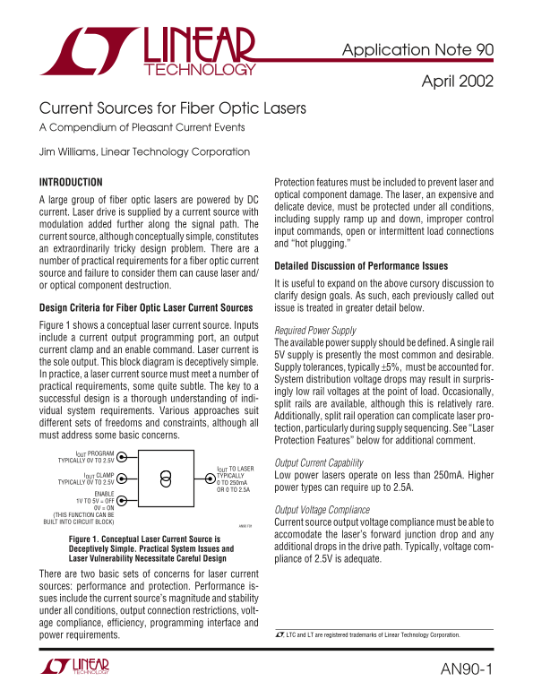
Design Criteria for Fiber Optic Laser Current Sources issue is treated in greater detail below. Figure 1 shows a conceptual laser current source. Inputs

Required Power Supply

include a current output programming port, an output

The available power supply should be defined. A single rail

current clamp and an enable command. Laser current is

5V supply is presently the most common and desirable.

the sole output. This block diagram is deceptively simple.

Supply tolerances, typically ±5%, must be accounted for.

In practice, a laser current source must meet a number of

System distribution voltage drops may result in surpris-

practical requirements, some quite subtle. The key to a

ingly low rail voltages at the point of load. Occasionally,

successful design is a thorough understanding of indi-

split rails are available, although this is relatively rare.

vidual system requirements. Various approaches suit

Additionally, split rail operation can complicate laser pro-

different sets of freedoms and constraints, although all

tection, particularly during supply sequencing. See “Laser

must address some basic concerns.

Protection Features” below for additional comment.

IOUT PROGRAM TYPICALLY 0V TO 2.5V

Output Current Capability

IOUT TO LASER

IOUT CLAMP TYPICALLY Low power lasers operate on less than 250m A. Higher TYPICALLY 0V TO 2.5V 0 TO 250m A

OR 0 TO 2.5A power types can require up to 2.5A.

ENABLE 1V TO 5V = OFF 0V = ON

Output Voltage Compliance

(THIS FUNCTION CAN BE BUILT INTO CIRCUIT BLOCK) Current source output voltage compliance must be able to

AN90 F01

accomodate the laser’s forward junction drop and any

Figure 1. Conceptual Laser Current Source is

Deceptively Simple. Practical System Issues and additional drops in the drive path. Typically, voltage com-

Laser Vulnerability Necessitate Careful Design pliance of 2.5V is adequate. There are two basic sets of concerns for laser current sources: performance and protection. Performance is- sues include the current source’s magnitude and stability under all conditions, output connection restrictions, volt- age compliance, efficiency, programming interface and

power requirements. , LTC and LT are registered trademarks of Linear Technology Corporation.

AN90-1

Page Summary Contents For LINEAR AN90-1 Data Handbook

Page 1 Application Note 90 April 2002 Current Sources for Fiber Optic Lasers A Compendium of Pleasant Current Events Jim Williams, Linear Technology Corporation INTRODUCTION Protection features must be inclu...
Page 2 Application Note 90 Efficiency Detailed Discussion of Laser Protection Issues Heat build up in fiber optic systems is often a concern due to space limitations. Accordingly, current source effi- Oversh...
Page 3 Application Note 90 application. The designs can be directly utilized or serve as proach 1W under some conditions. Many applications starting points for specific cases. permit this but some situations...
Page 4 Application Note 90 ENABLE 10k VCC IMAX L1SHDN OFF = 1V TO 5V 2N3904 FB LTC1504A VSW ON = 0V = 1% METAL FILM RESISTOR 0.01µF L1 = 47µH, SUMIDA CD54-470 = LASER LT1006 INPUT 80.6k*10k* 0V TO 2.5V = 0m ...
Page 5 Application Note 90 input’s setting. At laser voltages equaling or above the Fully Protected, Self-Enabled, Grounded Cathode VCLAMP input, A1 is a voltage source, controlled by VCLAMP’s Current Source...
Page 6 Application Note 90 INPUT 2.5k 10k 5V 0V TO 2.5V = 0m A TO 250m A A1 Q1 0.02µF 1/2 LT1013 10k FZT-849 1/2 LT1013 2N3906 50k COLL REF CLAMP ADJUST LT1004 CURRENT +A3 CLAMP LT1789RG LT1431 2.5V SELF-ENA...
Page 7 Application Note 90 Figure 10 shows what happens when the circuit is turned A final protection feature in Figure 6 is a current clamp. It on into an open laser connection. Trace assignments are preven...
Page 8 Application Note 90 be particularly fast to be effective, because of A1’s 10k- forms detail dynamic response. Trace A’s input step 0.02µF input filter. Figure 11’s traces show clamp re- arrives in fil...
Page 9 Application Note 90 BOOST VIN VSW 3k LTC1506 MBR330 300µF FROM OPTIONAL FB OPEN LASER PROTECTION CIRCUITRY OUTPUT. SEE FIGURE 6 A1 LT1006 INPUT 10k 0V TO 2.5V = 0A TO 2.5A 0.33µF 2N3904 ENABLE FOR OPT...
Page 10 Application Note 90 AT THIS POINT VIN GCL 68µF V+ 5V LT1054 LT1683 GATE A Q1 SYNC CAP A CAP B RVSL GATE B Q2 PGND FROM OPTIONAL 330Ω OPEN LASER FB PROTECTION OUTPUT. 0.01µF SEE FIGURE 6 SS GND NFB ENA...
Page 11 Application Note 90 the LT1683 controller. In practice, these resistor values ripple residue and switching artifacts are visible against are set by adjusting them to minimize output noise. The the mea...
Page 12 Application Note 90 PGND RT CT T1 FB COL A LT1533 5V COL B RCSL RVSL VC SHDN FROM OPTIONAL OPEN LASER 1Ω PROTECTION. 14k 14k 1% SEE FIGURE 6 10k 0.01µF TO LT1533 SHUTDOWN PIN FOR OPTIONAL SELF-ENABLE ...
Page 13 Application Note 90 Low Noise, Fully Floating Output Current Source The schematic shows the LT1533 low noise switching regulator driving T1. The LT1533, while retaining its Figure 19 retains the prece...
Page 14 Application Note 90 difference between the output current programming input Because the LTC1696 output latches, power must be and A2’s amplified version of the shunt voltage. This loop recycled to res...
Page 15 Application Note 90 nents also prevent unwanted outputs when the supply Trace B, C1’s output, responds briefly but goes low some rises rapidly. Such rapid rise could cause uncontrolled A1 time after t...
Page 16 Application Note 90 The slew retarded input and loop compensation yield clean Current clamping and open laser protection options are dynamic response with no overshoot. Figure 24, trace A, annotated i...
Page 17 Application Note 90 APPENDIX A SIMULATING THE LASER LOAD Fiber optic lasers are a delicate, unforgiving and expensive Electronic Laser Load Simulator load. This is a poisonous brew when breadboarding ...
Page 18 Application Note 90 APPENDIX B VERIFYING SWITCHING REGULATOR RELATED NOISE Measuring the switching regulator related current noise Figure B1’s test setup allows investigation of the closed levels disc...
Page 19 Application Note 90 comparable to the previously determined noise floor but accomplished by coupling to the field produced by the the trace, clearly delineated against the noise limit, indi- switching...
Page 20 Application Note 90 Trigger Probe Amplifier output signal appears at the junction of the 500p F capaci- tor and the 3MΩ units. This point always sits midway The field around the switching magnetics is...
Page 21 Application Note 90 10m V/DIV 10m V/DIV 10µs/DIV AN90 FB07 10µs/DIV AN90 FB08 Figure B7. Misadjusted Termination Causes Inadequate Figure B8. Properly Adjusted Termination Damping. Unstable Oscillosco...
Page 22 Application Note 90 APPENDIX C NOTES ON CURRENT PROBES AND NOISE MEASUREMENT Appendix B explained current probes advantages in switch- Figure C2 shows the CT-1 (closed core)-HP461A combi- ing regulato...
Page 23 Application Note 90 A = 100µA/DIV 500ns/DIV Figure C2. CT-1/HP-461A Combination Clearly Displays a 100µA Pulse Train. Noise Floor Causes Slight Pulse Top and Bottom Trace Thickening A = 100µA/DIV 500n...
Page 24 Application Note 90 an90f LT/TP 0402 2K • PRINTED IN USA Linear Technology Corporation AN90-24 1630 Mc Carthy Blvd., Milpitas, CA 95035-7417 (408) 432-1900 ● FAX: (408) 434-0507 ● www.linear.com  LIN...

Manual Details

Brand Linear
Pages 24
File Size 399.22 KB
Published June 03, 2026
55 views

Enter the captcha to get the download link:

captcha

Frequently Asked Questions

What basic concerns must laser current sources address?

They must address performance and protection issues.

Are specific voltage rails necessary for the power supply?

While split rails are sometimes available, single-rail operation can be maintained using specialized techniques like switching regulators if careful design is implemented.

How is the output current controlled?

The output current is set by a programming port voltage (0A to 250mA or 0A to 2.5A).

What are critical safety precautions for laser components?

Protection features must be included to prevent damage from overcurrent, improper control modulation, and open/intermittent load connections.