LINEAR AN108-1 Data Handbook
Summary
LTC3207/3207-1 are 600mA I2C-controlled LED/camera flash drivers illuminating 12 individually configurable ULEDs (on/off, blink, gradation) plus a camera flash LED. Features 16 data registers, external enable pin, and charge pump with auto/1x/1.5x/2x modes. Targets hardware engineers developing camera lighting for mobile phones and portable devices.
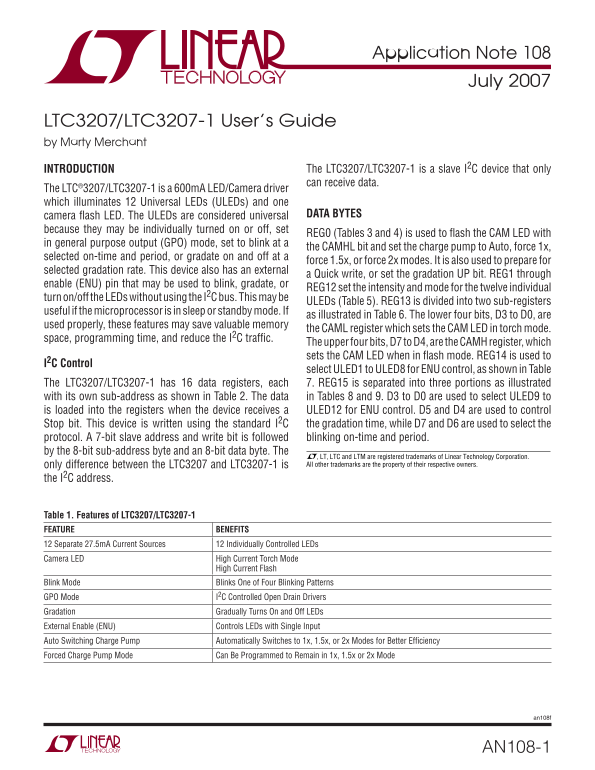
Page 1 Text Content
Application Note 108
July 2007
LTC3207/LTC3207-1 User’s Guide by Marty Merchant
INTRODUCTION The LTC3207/LTC3207-1 is a slave I2C device that only can receive data.
The LTC®3207/LTC3207-1 is a 600m A LED/Camera driver which illuminates 12 Universal LEDs (ULEDs) and one
camera fl ash LED. The ULEDs are considered universal DATA BYTES
because they may be individually turned on or off, set
REG0 (Tables 3 and 4) is used to fl ash the CAM LED with
in general purpose output (GPO) mode, set to blink at a
the CAMHL bit and set the charge pump to Auto, force 1x,
selected on-time and period, or gradate on and off at a
force 1.5x, or force 2x modes. It is also used to prepare for
selected gradation rate. This device also has an external
a Quick write, or set the gradation UP bit. REG1 through
enable (ENU) pin that may be used to blink, gradate, or
REG12 set the intensity and mode for the twelve individual
turn on/off the LEDs without using the I2C bus. This may be
ULEDs (Table 5). REG13 is divided into two sub-registers
useful if the microprocessor is in sleep or standby mode. If
as illustrated in Table 6. The lower four bits, D3 to D0, are
used properly, these features may save valuable memory
the CAML register which sets the CAM LED in torch mode.
space, programming time, and reduce the I2C traffi c.
The upper four bits, D7 to D4, are the CAMH register, which sets the CAM LED when in fl ash mode. REG14 is used to
I2C Control
select ULED1 to ULED8 for ENU control, as shown in Table
The LTC3207/LTC3207-1 has 16 data registers, each 7. REG15 is separated into three portions as illustrated with its own sub-address as shown in Table 2. The data in Tables 8 and 9. D3 to D0 are used to select ULED9 to is loaded into the registers when the device receives a ULED12 for ENU control. D5 and D4 are used to control Stop bit. This device is written using the standard I2C the gradation time, while D7 and D6 are used to select the protocol. A 7-bit slave address and write bit is followed blinking on-time and period. by the 8-bit sub-address byte and an 8-bit data byte. The
, LT, LTC and LTM are registered trademarks of Linear Technology Corporation. only difference between the LTC3207 and LTC3207-1 is All other trademarks are the property of their respective owners.
the I2C address.
Table 1. Features of LTC3207/LTC3207-1 FEATURE BENEFITS 12 Separate 27.5m A Current Sources 12 Individually Controlled LEDs Camera LED High Current Torch Mode
High Current Flash
Blink Mode Blinks One of Four Blinking Patterns GPO Mode I2C Controlled Open Drain Drivers Gradation Gradually Turns On and Off LEDs External Enable (ENU) Controls LEDs with Single Input Auto Switching Charge Pump Automatically Switches to 1x, 1.5x, or 2x Modes for Better Effi ciency Forced Charge Pump Mode Can Be Programmed to Remain in 1x, 1.5x or 2x Mode
an108f
AN108-1
Page Summary Contents For LINEAR AN108-1 Data Handbook
Manual Details
| Brand | Linear |
|---|---|
| Pages | 8 |
| File Size | 85.78 KB |
| Published | June 15, 2026 |
Enter the captcha to get the download link:

Frequently Asked Questions
What is the maximum current rating of the LTC3207?
The LTC3207/LTC3207-1 is a 600mA LED/Camera driver.
How many individually controlled LEDs does the LTC3207 support?
It illuminates 12 Universal LEDs and one camera flash LED.
How do I disable ENU and gradation control initially?
Set ENU pin high, clear ENU control bits without Stop, clear gradation timer bits without Stop, set ULED intensity with gradation bit low then send Stop.
What is the I2C address difference between LTC3207 and LTC3207-1?
The only difference between the two models is their I2C slave address.