# A B C D E F G H I J K L M N O P Q R S T U V W X Y Z

HITACHI 2SJ317 Data Sheet/Manual

Summary

Engineered for high-speed, low-voltage power switching, this P-Channel MOSFET is ideal for professional electronic designs requiring reliable energy management. Applicable in motor drives, solenoid circuits, and general power switching arrays, it features very low on-resistance and robust performance across varying temperatures. This comprehensive datasheet provides electrical engineers and designers with detailed technical specifications, including absolute maximum ratings, breakdown voltages, switching characteristics, and thermal operational curves necessary for optimal circuit integration and reliable system performance.
📄 Preview PAGE OF 9

Page 1 Text Content

查询2SJ317供应商

2SJ317 Silicon P-Channel MOS FET

Application

High speed power switching

Low voltage operation

Features

• Very low on-resistance • High speed switching • Suitable for camera or VTR motor drive circuit, power switch, solenoid drive and etc.

Outline

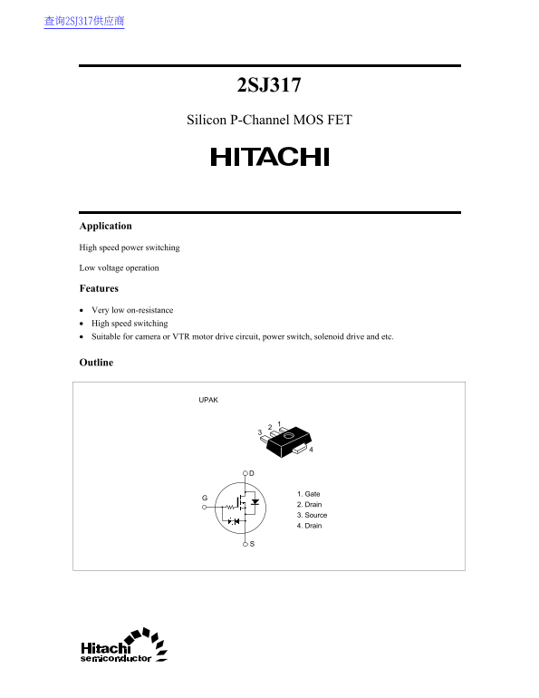
1. Gate 2. Drain 3. Source 4. Drain

Page Summary Contents For HITACHI 2SJ317 Data Sheet/Manual

Page 1 查询2SJ317供应商 2SJ317 Silicon P-Channel MOS FET Application High speed power switching Low voltage operation Features • Very low on-resistance • High speed switching • Suitable for camera or VTR motor dr...
Page 2 2SJ317 Absolute Maximum Ratings (Ta = 25°C) Item Symbol Ratings Unit Drain to source voltage VDSS –12 Gate to source voltage VGSS –7 Drain current ID ±2 Drain peak current ID(pulse)* ±4 Body to drain ...
Page 3 2SJ317 ha nn el ow er is si pa tio ch ra in ur re nt (o th al um in am er am ic oa rd Maximun Power Dissipation Curve Maximun Safe Operation Area 2.0 –10 Operation in this Area PW = 1 ms is limited by...
Page 4 2SJ317 ra in to ou rc at ur at io ol ta ge or ar ra ns fe dm itt an ce | ( (o n) Forward Transfer Admittance vs. Drain to Source on State Resistance Drain Current vs. Drain Current V = –5 V Pulse test...
Page 5 2SJ317 ra in to ou rc ol ta ge ev er se ec ov er im rr ns Reverse Recovery Time vs. Reverse Drain Current Switching Time vs. Drain Current tf td(off) V = –4 V GS V = –10 V DD PW = 5 µs Duty cycle 1 % ...
Page 6 2SJ317 Reverse Drain Current vs. Source to Drain Voltage –4 Pulse test V = –4 VGS –3 ev er se ra in ur re nt V = 0 VGS –0.5 –1.0 –1.5 –2.0 Source to Drain Voltage V (V) SD
Page 7 0. in 2. 0. 0. 4. ax Unit: mm 1.8 Max (1.5) 0.44 Max 0.53 Max 0.44 Max0.48 Max Hitachi Code UPAK JEDEC EIAJ Conforms Weight (reference value) 0.050 g
Page 8 Cautions 1. Hitachi neither warrants nor grants licenses of any rights of Hitachi’s or any third party’s patent, copyright, trademark, or other intellectual property rights for information contained i...
Page 9 WWW.ALLDATASHEET.COM Copyright © Each Manufacturing Company. All Datasheets cannot be modified without permission. This datasheet has been download from : www.All Data Sheet.com 100% Free Data Sheet S...

Manual Details

Brand Hitachi
Pages 9
File Size 39.55 KB
Published June 03, 2026
33 views

Enter the captcha to get the download link:

captcha

Frequently Asked Questions

What is the maximum allowable power dissipation of the device?

The channel can handle a continuous dissipation up to 1 Watt (Pch*).

What kind of applications are suitable for this FET?

It is highly suitable for motor drive circuits, general power switching, and solenoid drives.

What is the DC on-state resistance (R DS(on)) typical value?

The typical on-state resistance measured at I = –0.5 A is 0.7 Ohm.

How fast can this MOSFET switch off?

The turn-off time (t_d) is specified to be 2860 nanoseconds.