Vishay 31GF4 Datasheet
Summary
This high-performance semiconductor rectifier is an ultrafast plastic component engineered for efficient power conversion in demanding electrical systems. The associated manual provides exhaustive technical documentation necessary for integrated circuit design, detailing critical parameters such as maximum repetitive reverse voltage, average forward current (3.0A), thermal resistance, and surge withstand capabilities across various operating temperatures. It is the essential resource for electronics engineers and professional technicians selecting reliable components that require high efficiency and long-term operational stability in power electronics applications.
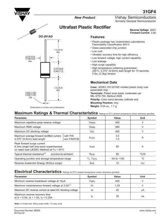
Page 1 Text Content
31GF4
New Product Vishay Semiconductors
formerly General Semiconductor
Ultrafast Plastic Rectifier
Reverse Voltage 400V Forward Current 3.0A
DO-201AD Features
• Plastic package has Underwriters Laboratories Flammability Classification 94V-0 • Glass passivated chip junction
• Low cost
• Ultrafast recovery time for high efficiency
• Low forward voltage, high current capability
0.190 (4.8) Dia. • Low leakage
• High surge capability 0.375 (9.5) • High temperature soldering guaranteed: 0.285 (7.2) 250°C, 0.375" (9.5mm) lead length for 10 seconds, 5 lbs. (2.3kg) tension
Mechanical Data 1.0 (25.4) Case: JEDEC DO-201AD molded plastic body over Min. passivated chip
Terminals: Plated axial leads, solderable per
MIL-STD-750, Method 2026
Polarity: Color band denotes cathode end Mounting Position: Any Weight: 0.04 oz., 1.1 g
Dimensions in inches and (millimeters)
Maximum Ratings & Thermal Characteristics Ratings at 25°C ambient temperature unless otherwise specified. Parameter Symbol Value Unit Maximum repetitive peak reverse voltage VRRM Maximum RMS voltage VRMS Maximum DC blocking voltage VDC Maximum average forward rectified current, with FIN 3.0
IF(AV)
0.375" (9.5mm) lead length w/o FIN/PCB 1.5 Peak forward surge current 8.3ms single half sine-wave superimposed IFSM on rated load (JEDEC Method) at TA = 55°C Typical thermal resistance(1) Junction-to-ambient RθJA °C/W Operating junction and storage temperature range TJ, TSTG –40 to +150 °C Reverse Avalanche Energy (8/20µs surge) EAR m J
Electrical Characteristics Ratings at 25°C ambient temperature unless otherwise specified. Parameter Symbol Value Unit Minimum reverse breakdown voltage at 10µA V(BR) Maximum instantaneous forward voltage at 3.0A(1) VF 1.25 Maximum DC reverse current at rated DC blocking voltage IR µA Maximum reverse recovery time
trr ns
at IF = 0.5A, IR = 1.0A, Irr = 0.25A
Note: (1) Pulse test: 300µs pulse width, 1% duty cycle
Document Number 88529 www.vishay.com 28-Feb-02
Page Summary Contents For Vishay 31GF4 Datasheet
Manual Details
| Brand | Vishay |
|---|---|
| Pages | 2 |
| File Size | 20.15 KB |
| Published | June 02, 2026 |
Enter the captcha to get the download link:

Frequently Asked Questions
What is the maximum allowable repetitive peak reverse voltage?
It has a maximum repetitive peak reverse voltage (V_RRM) of 400 V.
What operating temperature range should I account for when using this component?
The operating junction and storage temperature range (T_J) is from -40 to +150°C.
How high can the device withstand a momentary electrical surge?
It has a Peak forward surge current of 60 A when tested for 8.3ms on a rated load.
What physical requirements must I follow when mounting this device?
The specified mounting position is "Any," and it ships with plated axial leads designed to be solderable.