Toshiba TLP114A User's Guide
Summary
The TLP114A is a miniature, high-performance optocoupler ideal for robust digital logic isolation in general electronic applications. This manual serves as a comprehensive resource for engineers, detailing full electrical characteristics, including maximum ratings, precise transfer ratios, and critical specifications like switching times ($t_{HL}/t_{LH}$) and high voltage isolation resistance (3750 Vrms). Use this guide to ensure reliable signal coupling and power supply control within industrial, computational, or office equipment designs.
Page 1 Text Content
查询TLP114A供应商
TLP114A
TOSHIBA Photocoupler Ga AℓAs Ired & Photo−IC
TLP114A
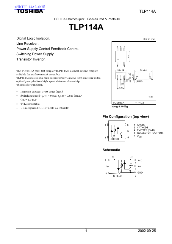
Digital Logic Isolation. Unit in mm Line Receiver. Power Supply Control Feedback Control. Switching Power Supply. Transistor Invertor.
The TOSHIBA mini flat coupler TLP114A is a small outline coupler, suitable for surface mount assembly. TLP114A consists of a high output power Ga AℓAs light emitting didoe, optically coupled to a high speed detector of one chip photodiode-transistor.
Isolation voltage: 3750 Vrms (min.) Switching speed: tp HL = 0.8µs, tp LH = 0.8µs (max.) (RL = 1.9 kΩ)
TOSHIBA 11−4C2
TTL compatible
Weight: 0.09g
UL recognized: UL1577, file no. E67349
Pin Configuration (top view)
1 : ANODE 3 : CATHODE 4 : EMITTER (GND) 5 : COLLECTOR (OUTPUT). 6 : VCC 4
SHIELD
Schematic IF ICC
VCC IO 6 VO
SHIELD
Page Summary Contents For Toshiba TLP114A User's Guide
Manual Details
| Brand | Toshiba |
|---|---|
| Pages | 7 |
| File Size | 157.26 KB |
| Published | June 01, 2026 |
Enter the captcha to get the download link:
