Toshiba TLP114A(IGM) Specifications
Summary
The TLP114A(IGM) is a miniature, high-isolation photocoupler ideal for surface mount applications that require signal integrity. Featuring an integrated Faraday shield and advanced GaAℓAs LED technology, it guarantees superior common mode transient immunity and robust isolation up to 3750V rms. This manual provides comprehensive technical data, including maximum ratings, detailed electrical characteristics, switching timing, and transfer ratios. It is specifically engineered for dependable signal interface solutions between Intelligent Power Modules (IPM) and control ICs in demanding motor control applications.
Page 1 Text Content
查询TLP114AIGM供应商
TLP114A(IGM)
TOSHIBA Photocoupler Ga AℓAs Ired + Photo−IC TENTATIVE
TLP114A(IGM)
Transistor Invertor Unit in mm Inverter For Air Conditioner Line Receiver Ipm Interfaces
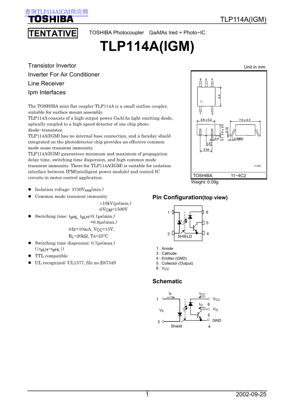
The TOSHIBA mini flat coupler TLP114A is a small outline coupler, suitable for surface mount assembly. TLP114A consists of a high output power Ga AℓAs light emitting diode, optically coupled to a high speed detector of one chip photo diode−transistor. TLP114A(IGM) has no internal base connection, and a faraday shield integrated on the photodetector chip provides an effective common mode noise transient immunity. TLP114A(IGM) guarantees minimum and maximum of propagation delay time, switching time dispersion, and high common mode transient immunity. There for TLP114A(IGM) is suitable for isolation interface between IPM(intelligent power module) and control IC
TOSHIBA 11−4C2
circuits in motor control application.
Weight: 0.09g
Isolation voltage: 3750Vrms(min.) Common mode transient immunity Pin Configuration(top view) : ±10k V/µs(min.) @VCM=1500V Switching time: tp HL, tp LH=0.1µs(min.) =0.8µs(max.) @IF=10m A, VCC=15V, RL=20kΩ, Ta=25°C SHIELD Switching time dispersion: 0.7µs(max.)
(|tp LH−tp HL|) 1 : Anode 3 : Cathode
TTL compatible
4 : Emitter (GND)
UL recognized: UL1577, file no.E67349 5 : Collector (Output)
6 : VCC
Schematic IF ICC
VCC IO 6 VO
Shield
Page Summary Contents For Toshiba TLP114A(IGM) Specifications
Manual Details
| Brand | Toshiba |
|---|---|
| Pages | 7 |
| File Size | 152.94 KB |
| Published | June 15, 2026 |
Enter the captcha to get the download link:

Frequently Asked Questions
What is the isolation voltage of the TLP114A?
The minimum specified isolation voltage (BV) is 3750 Vrms.
How can I use this for motor control applications?
It is suitable for providing an isolation interface between Intelligent Power Modules (IPM) and control IC circuits in motor control applications.
What is the recommended coupling usage rate?
The current transfer ratio is rated at 25% to 35% when I = 10mA and V=4.5V.
Does it have high common mode noise immunity?
Yes, the transient immunity is guaranteed minimum of ±10kV/µs (minimum) at V = 1500V (minimum).