Toshiba TLP113 User's Guide
Summary
The TLP113 is a high-isolation, mini flat optocoupler designed for reliable digital signal transmission and electrical isolation up to 2500Vrms. This comprehensive datasheet provides engineers with all necessary technical specifications, including maximum ratings, advanced electrical characteristics, switching times, and common mode transient immunity data. It is ideal for electronics designers creating industrial controls, computer peripherals, or measuring equipment that requires high-quality signal integrity and robust isolation.
Page 1 Text Content
查询TLP113供应商
TLP113
TOSHIBA Photocoupler Ga AℓAs IRed & Photo−IC
TLP113
Isolated Line Receiver Simplex / Multiplex Data Transmission
Unit in mm
Computer−Peripheral Interface Microprocessor System Interface Digital Isolation For A / D, D / A Conversion
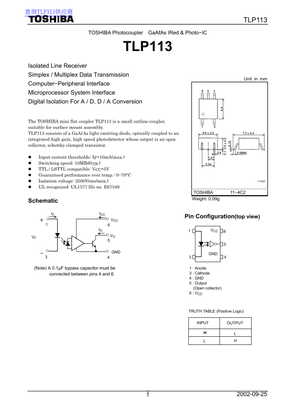
The TOSHIBA mini flat coupler TLP113 is a small outline coupler, suitable for surface mount assembly. TLP113 consists of a Ga AℓAs light emitting diode, optically coupled to an integrated high gain, high speed photodetector whose output is an open collector, schottky clamped transistor.
Input current thresholds: IF=10m A(max.) Switching speed: 10MBd(typ.) TTL / LSTTL compatible: VCC=5V Guaranteed performance over temp.: 0~70°C Isolation voltage: 2500Vrms(min.) UL recognized: UL1577 file no. E67349
TOSHIBA 11−4C2 Weight: 0.09g
Schematic
IF ICC
Pin Configuration(top view)
(Note) A 0.1µF bypass capacitor must be 1 : Anode
connected between pins 4 and 6. 3 : Cathode 4 : GND 5 : Output (Open collector) 6 : VCC
TRUTH TABLE (Positive Logic)
INPUT OUTPUT
Page Summary Contents For Toshiba TLP113 User's Guide
Manual Details
| Brand | Toshiba |
|---|---|
| Pages | 8 |
| File Size | 216.33 KB |
| Published | June 04, 2026 |
Enter the captcha to get the download link:

Frequently Asked Questions
What capacitor needs to be connected between pins 4 and 6?
A 0.1µF bypass capacitor must be connected between pins 4 and 6.
What is the minimum isolation voltage rating?
The device guarantees a minimum isolation voltage of 2500Vrms.
What are the operating temperature ranges for the TLP113?
The operating range (opr) is from -40°C to 85°C, while the storage range (stg) is -55°C to 125°C.
Can this product be used in medical or safety-critical equipment?
No, it is not intended for use in medical instruments, all types of safety devices, or other equipment requiring extraordinarily high reliability.