Toshiba TPC8111 User's Guide
Summary
The TPC8111 is a high-efficiency silicon P-Channel MOSFET transistor optimized for power management in portable electronics, including Li-ion batteries, notebooks, and personal equipment. Known for its small footprint, low drain-source ON resistance (R=8.1 mΩ), and low leakage current, it ensures reliable performance in space-constrained systems. This technical manual provides comprehensive engineering data, detailing maximum electrical ratings, thermal characteristics, and operational parameters required for system designers integrating this power component into their designs.
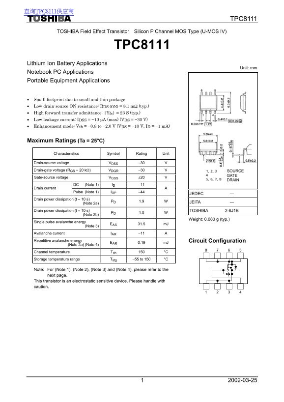
Page 1 Text Content
查询TPC8111供应商
TPC8111
TOSHIBA Field Effect Transistor Silicon P Channel MOS Type (U-MOS IV)
TPC8111
Lithium Ion Battery Applications
Unit: mm
Notebook PC Applications Portable Equipment Applications
• Small footprint due to small and thin package • Low drain-source ON resistance: RDS (ON) = 8.1 mΩ (typ.) • High forward transfer admittance: |Yfs| = 23 S (typ.) • Low leakage current: IDSS = −10 µA (max) (VDS = −30 V) • Enhancement-mode: Vth = −0.8 to −2.0 V (VDS = −10 V, ID = −1 m A)
Maximum Ratings (Ta = 25°C)
Characteristics Symbol Rating Unit
Drain-source voltage VDSS −30 V Drain-gate voltage (RGS = 20 kΩ) VDGR −30 V Gate-source voltage VGSS ±20 V
DC (Note 1) ID −11
Drain current
Pulse (Note 1) IDP −44
JEDEC ―
Drain power dissipation (t = 10 s)
JEITA ―
(Note 2a) PD 1.9 W Drain power dissipation (t = 10 s) TOSHIBA 2-6J1B (Note 2b) PD 1.0 W
Weight: 0.080 g (typ.)
Single pulse avalanche energy (Note 3) EAS 31.5 m J Avalanche current IAR −11 A Repetitive avalanche energy Circuit Configuration (Note 2a) (Note 4) EAR 0.19 m J
Channel temperature Tch 150 °C 8 6 Storage temperature range Tstg −55 to 150 °C
Note: For (Note 1), (Note 2), (Note 3) and (Note 4), please refer to the next page. This transistor is an electrostatic sensitive device. Please handle with caution.
Page Summary Contents For Toshiba TPC8111 User's Guide
Manual Details
| Brand | Toshiba |
|---|---|
| Pages | 7 |
| File Size | 392.16 KB |
| Published | June 02, 2026 |
Enter the captcha to get the download link:

Frequently Asked Questions
How must this component be handled during installation?
This transistor is an electrostatic sensitive device, and users must handle it with caution.
What are the thermal constraints for operation?
Devices must be operated under conditions where the channel temperature remains below 150°C.
What is the typical drain-source ON resistance (Rds(on)) rating?
The typical Rds(on) value is 8.1 mΩ at operating conditions listed in the electrical characteristics.
Is this component suitable for critical safety systems?
No; it is not warranted for "Unintended Usage" like medical instruments or aircraft systems, which require exceptionally high reliability.