# A B C D E F G H I J K L M N O P Q R S T U V W X Y Z

Texas Instruments UCD8220, UCD8620 User's Manual and Specifications

Summary

The UCD8220 and UCD8620 are advanced, digitally managed push-pull PWM controllers designed for implementing sophisticated power supplies. These high-performance components support applications like battery chargers and switch mode converters that require precise digital control. The manual provides comprehensive technical documentation, including integration guides, schematics for half-bridge/push-pull topologies, and details on programmable current limit features compatible with microcontrollers and DSPs. This resource is essential for electrical engineers developing complex power management systems requiring high stability and controllability.
📄 Preview PAGE OF 32

Page 1 Text Content

查询UCD8220供应商

UCD8220, UCD8620

www.ti.com

SLUS652B–MARCH 2005–REVISED SEPTEMBER

DIGITALLY MANAGED PUSH-PULL ANALOG PWM CONTROLLERS

FEATURES 10-ns Typical Rise and Fall Times with 2.2-n F

For Digitally Managed Power Supplies Using 25-ns Input-to-Output Propagation Delay

µCs or the TMS320 DSP Family

25-ns Current Sense-to-Output Propagation

Voltage or Peak Current Mode Control with Delay

Cycle-by-Cycle Current Limiting

Programmable Current Limit Threshold

Clock input from Digital Controller to set

Digital Output Current Limit Flag

Operating Frequency and Max Duty Cycle

4.5-V to 15.5-V Supply Voltage Range

Analog PWM Comparator

Rated from -40°C to 105°C•

2-MHz Switching Frequency

110-V Input Startup Circuit and Thermal

APPLICATIONS

Shutdown (UCD8620)

Digitally Managed Switch Mode Power

Internal Programmable Slope Compensation Supplies

3.3-V, 10-m A Linear Regulator Push-Pull, Half-Bridge, or Full-Bridge

Converters•

DSP/µC Compatible Inputs

Battery Chargers•

Dual ±4-A True Drive™ High Current Drivers

DESCRIPTION

The UCD8220 and UCD8620 are members of the UCD8K family of analog pulse-width modulator devices to be

used in digitally managed power supplies using microcontroller or the TMS320™ DSP family.

UCD8220 and UCD8620 are double-ended PWM controllers configured with push-pull drive logic. The UCD8620

has 110-V high-voltage startup circuit which can directly start up the controller from 48-V telecom input line.

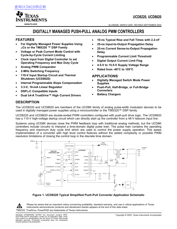
Systems using UCD8K devices close the PWM feedback loop with traditional analog methods, but the UCD8K

controllers include circuitry to interpret time-domain digital pulse train. The pulse train contains the operating

frequency and maximum duty cycle limit which are used to control the power supply operation. This eases

implementation of converter with high level control features without the added complexity or possible PWM

resolution limitations of closing the control loop in the discrete time domain.

Figure 1. UCD8220 Typical Simplified Push-Pull Converter Application Schematic

Please be aware that an important notice concerning availability, standard warranty, and use in critical applications of Texas

Instruments semiconductor products and disclaimers thereto appears at the end of this data sheet.

TMS320, True Drive, Power PAD are trademarks of Texas Instruments.

UNLESS OTHERWISE NOTED this document contains PRO- Copyright 2005, Texas Instruments Incorporated

DUCTION DATA information current as of publication date. Prod-

ucts conform to specifications per the terms of Texas Instruments

standard warranty. Production processing does not necessarily

include testing of all parameters.

Page Summary Contents For Texas Instruments UCD8220, UCD8620 User's Manual and Specifications

Page 1 查询UCD8220供应商 UCD8220, UCD8620 www.ti.com SLUS652B–MARCH 2005–REVISED SEPTEMBER DIGITALLY MANAGED PUSH-PULL ANALOG PWM CONTROLLERS FEATURES 10-ns Typical Rise and Fall Times with 2.2-n F For Digitally ...
Page 2 UCD8220, UCD8620 www.ti.com SLUS652B–MARCH 2005–REVISED SEPTEMBER DESCRIPTION (continued) The UCD8220 and UCD8620 can be configured for either peak current mode or voltage mode control. They provide p...
Page 3 UCD8220, UCD8620 www.ti.com SLUS652B–MARCH 2005–REVISED SEPTEMBER SIMPLIFIED APPLICATION DIAGRAMS (continued) Figure 3. UCD8620 Typical Simplified Push-Pull Converter Application Schematic Figure 4. U...
Page 4 UCD8220, UCD8620 www.ti.com SLUS652B–MARCH 2005–REVISED SEPTEMBER These devices have limited built-in ESD protection. The leads should be shorted together or the device placed in conductive foam durin...
Page 5 UCD8220, UCD8620 www.ti.com SLUS652B–MARCH 2005–REVISED SEPTEMBER PACKAGING INFORMATION POWER RATING TA RATING FACTOR PACKAGE SUFFIX θJC(°C/W) θJA(°C/W) 70°C, TJ 125°C ABOVE 70°C Power Pad™ PWP 2.07 3...
Page 6 UCD8220, UCD8620 www.ti.com SLUS652B–MARCH 2005–REVISED SEPTEMBER ELECTRICAL CHARACTERISTICS VDD V, 4.7-µF capacitor from VDD to AGND, µF from PVDD to PGND, 0.22-µF capacitor from 3V3 to AGND, TA TJ -...
Page 7 UCD8220, UCD8620 www.ti.com SLUS652B–MARCH 2005–REVISED SEPTEMBER ELECTRICAL CHARACTERISTICS (continued) VDD V, 4.7-µF capacitor from VDD to AGND, µF from PVDD to PGND, 0.22-µF capacitor from 3V3 to A...
Page 8 UCD8220, UCD8620 www.ti.com SLUS652B–MARCH 2005–REVISED SEPTEMBER FUNCTIONAL BLOCK DIAGRAMS 2CLK VDD 3V3 Regulator 33V3 and UVLO Reference DRIVE LOGIC ISET PWM 6CTRL PGND CURRENT LIMIT CURRENT 8ILIM C...
Page 9 UCD8220, UCD8620 www.ti.com SLUS652B–MARCH 2005–REVISED SEPTEMBER TERMINAL FUNCTIONS PIN NUMBER UCD8220 UCD8620PIN NAME I/O FUNCTION HTSSOP-16 QFN-16 HTSSOP-16 QFN-20 (PWP) (RSA) (PWP) (RGW) Clock. In...
Page 10 UCD8220, UCD8620 www.ti.com SLUS652B–MARCH 2005–REVISED SEPTEMBER fe re lt re ld TYPICAL CHARACTERISTICS UCD8220 UCD8620 UVLO THRESHOLD UVLO THRESHOLD vs vs TEMPERATURE TEMPERATURE UVLO on UVLO on UVL...
Page 11 UCD8220, UCD8620 www.ti.com ly rr SLUS652B–MARCH 2005–REVISED SEPTEMBER ly rr TYPICAL CHARACTERISTICS (continued) SUPPLY CURRENT SUPPLY CURRENT vs vs FREQUENCY (VDD V) FREQUENCY (VDD V) CLOAD = 10 n F...
Page 12 UCD8220, UCD8620 www.ti.com SLUS652B–MARCH 2005–REVISED SEPTEMBER is ll im ly rr TYPICAL CHARACTERISTICS (continued) SUPPLY CURRENT CLK INPUT THRESHOLD vs vs FREQUENCY (VDD V) TEMPERATURE CLK Input Ri...
Page 13 UCD8220, UCD8620 www.ti.com SLUS652B–MARCH 2005–REVISED SEPTEMBER ro ti la ll in tp ll im TYPICAL CHARACTERISTICS (continued) OUTPUT FALL TIME CLK to OUTx PROPAGATION DELAY RISING vs vs SUPPLY VOLTAGE...
Page 14 UCD8220, UCD8620 www.ti.com SLUS652B–MARCH 2005–REVISED SEPTEMBER ro ti la ro ti la TYPICAL CHARACTERISTICS (continued) CS TO OUTx PROPAGATION DELAY CS TO CLF PROPAGATION DELAY vs vs TEMPERATURE TEMPE...
Page 15 UCD8220, UCD8620 www.ti.com SLUS652B–MARCH 2005–REVISED SEPTEMBER TYPICAL CHARACTERISTICS (continued) UCD8620 UCD8220 START-UP BEHAVIOR AT VDD SHUT-DOWN BEHAVIOR AT VDD CLK = CTRL = 3V3 CLK = CTRL = 3...
Page 16 UCD8220, UCD8620 www.ti.com SLUS652B–MARCH 2005–REVISED SEPTEMBER TYPICAL CHARACTERISTICS (continued) UCD8620 UCD8220 START-UP BEHAVIOR AT VDD SHUT-DOWN BEHAVIOR AT VDD CLK = AGND CLK = AGND CTRL = 3V...
Page 17 UCD8220, UCD8620 www.ti.com SLUS652B–MARCH 2005–REVISED In te rn SEPTEMBER lo ti /m TYPICAL CHARACTERISTICS (continued) INTERNAL SLOPE COMPENSATION IN CMC PWM OFFSET AT CTRL INPUT vs vs TEMPERATURE TE...
Page 18 UCD8220, UCD8620 www.ti.com SLUS652B–MARCH 2005–REVISED SEPTEMBER APPLICATION INFORMATION operating frequency and maximum duty cycle limit Introduction and hence controls the power supply operation as...
Page 19 UCD8220, UCD8620 www.ti.com SLUS652B–MARCH 2005–REVISED SEPTEMBER Start up Steady State Current Limit UVLO and REF OK* CTRL RAMP* - Internal signals Figure 39. UCD8220 and UCD8620 Timing and Circuit O...
Page 20 UCD8220, UCD8620 www.ti.com ;y rr SLUS652B–MARCH 2005–REVISED SEPTEMBER (1) For VDD to go below V, the input supply must be dropping out. Figure 40. UCD8620 JFET Operation Waveforms Reference External...
Page 21 UCD8220, UCD8620 www.ti.com SLUS652B–MARCH 2005–REVISED SEPTEMBER When the CS voltage is below ILIM, the driver output restart the device in the event that it is not operating follows the PWM command....
Page 22 UCD8220, UCD8620 www.ti.com SLUS652B–MARCH 2005–REVISED SEPTEMBER Figure 43. ILIM Settings
Page 23 UCD8220, UCD8620 www.ti.com SLUS652B–MARCH 2005–REVISED SEPTEMBER IS is ta Selecting the ISET Resistor for Voltage Mode Figure shows the nominal value of resistance to Control use for desired clock fr...
Page 24 UCD8220, UCD8620 www.ti.com SLUS652B–MARCH 2005–REVISED SEPTEMBER Selecting the ISET Resistor for Peak Current The amount of slope compensation required depends Mode Control with Internal Slope Compen...
Page 25 UCD8220, UCD8620 www.ti.com SLUS652B–MARCH 2005–REVISED SEPTEMBER Reference [2] discusses the current required to drive ture range the package must allow for the efficient power MOSFET and other capac...
Page 26 UCD8220, UCD8620 www.ti.com SLUS652B–MARCH 2005–REVISED SEPTEMBER REFERENCES 1. Power Supply Seminar SEM-1600 Topic 6: Practical Introduction to Digital Power Supply Control, by Laszlo Balogh, Texas I...
Page 27 PACKAGE OPTION ADDENDUM www.ti.com 23-Sep-2005 PACKAGING INFORMATION Orderable Device Status Package Package Pins Package Eco Plan Lead/Ball Finish MSL Peak Temp Type Drawing Qty UCD8220PWP PREVIEW HT...
Page 28 PACKAGE OPTION ADDENDUM www.ti.com 3-Oct-2005 PACKAGING INFORMATION Orderable Device Status Package Package Pins Package Eco Plan Lead/Ball Finish MSL Peak Temp Type Drawing Qty UCD8220PWP ACTIVE HTSS...
Page 32 IMPORTANT NOTICE Texas Instruments Incorporated and its subsidiaries (TI) reserve the right to make corrections, modifications, enhancements, improvements, and other changes to its products and servic...

Manual Details

Brand Texas Instruments
Pages 32
File Size 2.33 MB
Published June 18, 2026
6 views

Enter the captcha to get the download link:

captcha

Frequently Asked Questions

Does UCD8620 support high voltage startup?

Yes, the UCD8620 includes an 110-V high-voltage startup circuit for direct start-up from a 48-V telecom line.

How is current limit monitored by the host controller?

The controller offers a programmable current limit threshold and uses a digital output current limit flag that can be monitored by the host controller.

What core control modes are available for these PWM controllers?

They can be configured for either peak current mode or voltage mode control, utilizing TrueDrive™ architecture for fast switching speeds.

What handling precautions should be taken during storage?

Because of limited built-in ESD protection, leads must be shorted together or the device stored in conductive foam to prevent damage.