Texas Instruments-ADS6149EVM Data Converter User's Manual and Technical Specifications
Summary
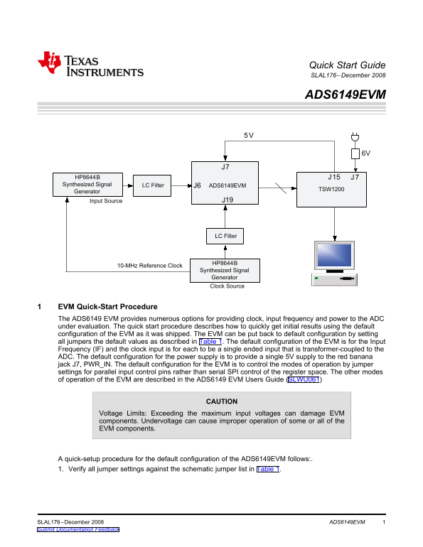
The ADS6149EVM is a comprehensive evaluation module designed to test and characterize Analog-to-Digital Converters (ADCs). This guide provides expert engineers and technical users with a quick-start procedure detailing how to achieve initial connection results using factory default settings. It covers essential setup steps, including verifying jumper configurations for power, clock input, and synthesized signal generation. Use this resource to efficiently validate ADC performance by providing controlled voltage sources and precise timing inputs.
Manual Details
| Brand | Texas Instruments |
|---|---|
| Pages | 3 |
| File Size | 57.27 KB |
| Published | May 28, 2026 |
Enter the captcha to get the download link:

Frequently Asked Questions
How do I get the EVM back to its starting default configuration?
Set all jumpers according to the default values provided in Table 1 of the manual.
What cautions should I follow regarding voltage limits when powering the board?
Exceeding maximum input voltages can damage components, and you must not connect a voltage source greater than 5.5 V.
What type of equipment is required to generate the clock signal for testing on J19?
Use a function generator with a 50-Ω output impedance, providing a 0-V offset sine-wave at the specified frequency.
Where must I connect a logic analyzer or TSW1200 to capture digital data results?
Connect the TSW1200 or suitable logic analyzer to pin J10 to capture the resulting digital data.