Texas Instruments SN65C3243, SN75C3243 User's Manual and Specifications
Summary
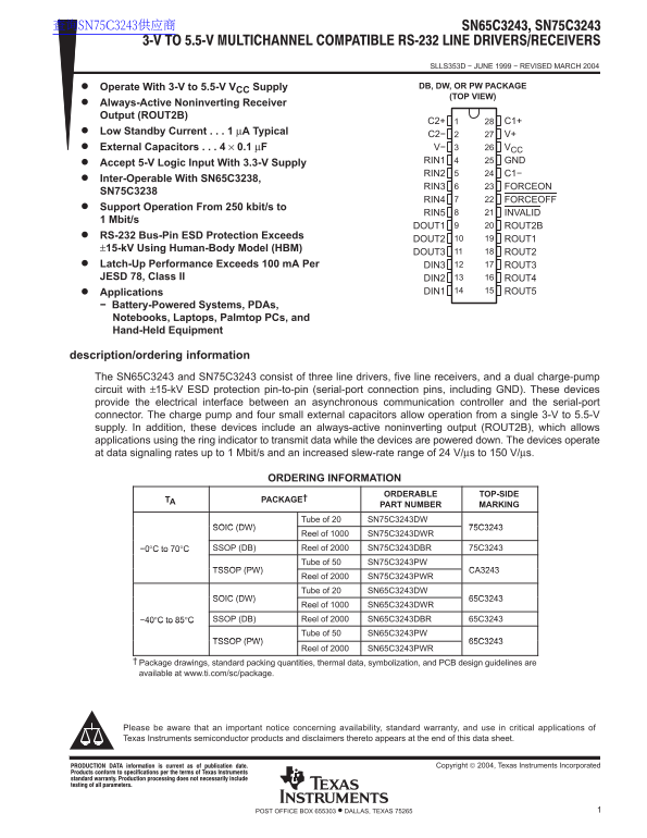
This datasheet describes the Texas Instruments SN65C3243 and SN75C3243 RS-232 interface devices containing three line drivers, five line receivers, and a dual charge-pump circuit. Operating from a single 3V to 5.5V supply, the charge pump requires only four 0.1µF external capacitors. An always-active noninverting receiver output (ROUT2B) enables ring indicator data transmission while the device is powered down. Standby current is just 1µA typical, and data signaling rates range from 250kbit/s to
Page 1 Text Content
查询SN75C3243供应商
SLLS353D − JUNE 1999 − REVISED MARCH 2004
Operate With 3-V to 5.5-V VCC Supply DB, DW, OR PW PACKAGE (TOP VIEW)
Always-Active Noninverting Receiver Output (ROUT2B)
Low Standby Current 1 µA Typical
C2− V+ External Capacitors 4 × 0.1 µF V− VCC
RIN1 GND
Accept 5-V Logic Input With 3.3-V Supply
RIN2 C1−
Inter-Operable With SN65C3238,
RIN3 FORCEON
SN75C3238
RIN4 FORCEOFF
Support Operation From 250 kbit/s to
RIN5 INVALID
1 Mbit/s
DOUT1 ROUT2B
RS-232 Bus-Pin ESD Protection Exceeds
DOUT2 ROUT1
±15-k V Using Human-Body Model (HBM)
DOUT3 ROUT2
Latch-Up Performance Exceeds 100 m A Per DIN3 ROUT3 JESD 78, Class II DIN2 ROUT4
Applications DIN1 ROUT5
− Battery-Powered Systems, PDAs, Notebooks, Laptops, Palmtop PCs, and Hand-Held Equipment
description/ordering information The SN65C3243 and SN75C3243 consist of three line drivers, five line receivers, and a dual charge-pump circuit with ±15-k V ESD protection pin-to-pin (serial-port connection pins, including GND). These devices provide the electrical interface between an asynchronous communication controller and the serial-port connector. The charge pump and four small external capacitors allow operation from a single 3-V to 5.5-V supply. In addition, these devices include an always-active noninverting output (ROUT2B), which allows applications using the ring indicator to transmit data while the devices are powered down. The devices operate at data signaling rates up to 1 Mbit/s and an increased slew-rate range of 24 V/µs to 150 V/µs.
ORDERING INFORMATION
ORDERABLE TOP-SIDE
TA PACKAGE†
PART NUMBER MARKING
Tube of 20 SN75C3243DW
SOIC (DW) 75C3243
Reel of 1000 SN75C3243DWR
−0°C to 70°C SSOP (DB) Reel of 2000 SN75C3243DBR 75C3243
Tube of 50 SN75C3243PW
TSSOP (PW) CA3243
Reel of 2000 SN75C3243PWR Tube of 20 SN65C3243DW
SOIC (DW) 65C3243
Reel of 1000 SN65C3243DWR
−40°C to 85°C SSOP (DB) Reel of 2000 SN65C3243DBR 65C3243
Tube of 50 SN65C3243PW
TSSOP (PW) 65C3243
Reel of 2000 SN65C3243PWR
Package drawings, standard packing quantities, thermal data, symbolization, and PCB design guidelines are available at www.ti.com/sc/package.
Please be aware that an important notice concerning availability, standard warranty, and use in critical applications of Texas Instruments semiconductor products and disclaimers thereto appears at the end of this data sheet.
!"#$% ! & '("") % $& ! *(+, '$% ! -$%) Copyright 2004, Texas Instruments Incorporated
1POST OFFICE BOX 655303 • DALLAS, TEXAS 75265
Page Summary Contents For Texas Instruments SN65C3243, SN75C3243 User's Manual and Specifications
Manual Details
| Brand | Texas Instruments |
|---|---|
| Pages | 15 |
| File Size | 241.59 KB |
| Published | June 19, 2026 |
Enter the captcha to get the download link:
