Texas Instruments CD54 74HC164, 74HCT164 User's Manual and Specifications
Summary
Discover the CD54/74HC164 family of 8-Bit Serial-In Parallel-Out Shift Registers. These high-speed CMOS logic ICs are essential components for transferring data within digital systems. This technical guide provides detailed specifications, including operating voltage ranges (2V to 6V), comprehensive pinouts, truth tables, and robust environmental ratings (-55°C to 125°C). Ideal for hardware engineers and system designers, this manual ensures proper integration of these reliable shift registers into complex digital circuit designs.
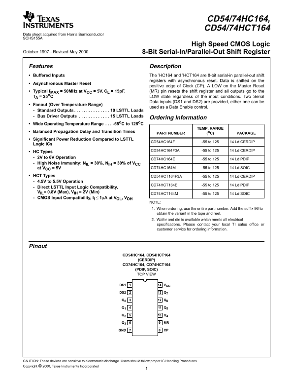
Page 1 Text Content
CD54/74HC164, CD54/74HCT164
Data sheet acquired from Harris Semiconductor SCHS155A
High Speed CMOS Logic
October 1997 - Revised May 2000 8-Bit Serial-In/Parallel-Out Shift Register
Features Description Buffered Inputs The ’HC164 and ’HCT164 are 8-bit serial-in parallel-out shift
registers with asynchronous reset. Data is shifted on the
[ /Title Asynchronous Master Reset
positive edge of Clock (CP). LOW on the Master Reset (CD74 Typical f MAX = 50MHz at VCC = 5V, CL = 15p F, (MR) pin resets the shift register and all outputs go to the
TA = 25o C LOW state regardless of the input conditions. Two Serial
HC164
Data inputs (DS1 and DS2) are provided, either one can be
Fanout (Over Temperature Range)
used as a Data Enable control.
CD74 Standard Outputs . . . . . . . . . . . . . . . 10 LSTTL Loads Bus Driver Outputs . . . . . . . . . . . . . 15 LSTTL Loads
HCT16 Ordering Information
4) Wide Operating Temperature Range . . . -55o C to 125o C
TEMP. RANGE
/Sub- Balanced Propagation Delay and Transition Times
PART NUMBER (o C) PACKAGE
ject Significant Power Reduction Compared to LSTTL
CD54HC164F -55 to 125 14 Ld CERDIP
(High Logic ICs
Speed CD54HC164F3A -55 to 125 14 Ld CERDIP
HC Types CMOS 2V to 6V Operation
CD74HC164E -55 to 125 14 Ld PDIP
High Noise Immunity: NIL = 30%, NIH = 30% of VCC
Logic
at VCC = 5V CD74HC164M -55 to 125 14 Ld SOIC
8-Bit
HCT Types CD54HCT164F3A -55 to 125 14 Ld CERDIP
Serial-
4.5V to 5.5V Operation
In/Par- CD74HCT164E -55 to 125 14 Ld PDIP
Direct LSTTL Input Logic Compatibility, allel- VIL= 0.8V (Max), VIH = 2V (Min)
CD74HCT164M -55 to 125 14 Ld SOIC
CMOS Input Compatibility, Il 1µA at VOL, VOH
NOTE: 1. When ordering, use the entire part number. Add the suffix to obtain the variant in the tape and reel. 2. Wafer and die is available which meets all electrical specifications. Please contact your local TI sales office or customer service for ordering information.
Pinout
CD54HC164, CD54HCT164
(CERDIP)
CD74HC164, CD74HCT164 (PDIP, SOIC) TOP VIEW
DS1 VCC
DS2 Q7
Q3 MR
GND CP
CAUTION: These devices are sensitive to electrostatic discharge. Users should follow proper IC Handling Procedures. Copyright © 2000, Texas Instruments Incorporated
Page Summary Contents For Texas Instruments CD54 74HC164, 74HCT164 User's Manual and Specifications
Manual Details
| Brand | Texas Instruments |
|---|---|
| Pages | 7 |
| File Size | 38.40 KB |
| Published | May 28, 2026 |
Enter the captcha to get the download link:

Frequently Asked Questions
What is the operating temperature range for these devices?
The devices operate within a wide range of -55 C to 125 C.
How do I reset the shift register data?
You can reset the register using an asynchronous Master Reset (MR) signal, which clears all outputs to L or low logic level.
What are the voltage requirements for HC and HCT types?
HC types operate from 2V to 6V. HCT types support 4.5V to 5.5V operation.
Can these ICs interface with different voltage levels?
The HCT type supports low-voltage signaling, making them compatible down to V = 0.8V (Max) and V = 2V (Min).
What precautions should be taken when handling these components?
Since these devices are sensitive to electrostatic discharge, users must follow proper IC Handling Procedures.