Texas Instruments CD54 74HC14, 74HCT14 datasheet user manual.
Summary
This datasheet provides comprehensive technical specifications for CD54/74HC14 and CD54/74HCT14 CMOS Logic Hex Inverting Schmitt Triggers. These reliable integrated circuits feature exceptional noise immunity and robust performance over a wide temperature range (-55°C to 125°C). The manual details electrical characteristics, timing diagrams, input/output compatibility (HC and HCT types), and usage guidelines for designing digital circuits requiring clear threshold switching from noisy signals. Ideal for engineers and circuit designers implementing high-speed, reliable logic interfaces.
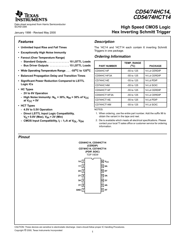
Page 1 Text Content
CD54/74HC14, CD54/74HCT14
Data sheet acquired from Harris Semiconductor SCHS129A High Speed CMOS Logic
January 1998 - Revised May 2000 Hex Inverting Schmitt Trigger
Features Description Unlimited Input Rise and Fall Times The ’HC14 and ’HCT14 each contain inverting Schmitt
Triggers in one package.
[ /Title Exceptionally High Noise Immunity
(CD74H Ordering Information
Fanout (Over Temperature Range) C14, Standard Outputs . . . . . . . . . . . . . . . 10 LSTTL Loads
TEMP. RANGE
CD74H Bus Driver Outputs . . . . . . . . . . . . . 15 LSTTL Loads PART NUMBER (o C) PACKAGE
CT14) Wide Operating Temperature Range . . . -55o C to 125o C
CD54HC14F -55 to 125 14 Ld CERDIP
/Subject
Balanced Propagation Delay and Transition Times CD54HC14F3A -55 to 125 14 Ld CERDIP
(High
Significant Power Reduction Compared to LSTTL CD74HC14E -55 to 125 14 Ld PDIP
Speed
Logic ICs
CD74HC14M -55 to 125 14 Ld SOIC
HC Types
CD54HCT14F -55 to 125 14 Ld CERDIP
Logic
2V to 6V Operation
Hex CD54HCT14F3A -55 to 125 14 Ld CERDIP
High Noise Immunity: NIL = 30%, NIH = 30% of VCC
Invert- CD74HCT14E -55 to 125 14 Ld PDIP
at VCC = 5V
CD74HCT14M -55 to 125 14 Ld SOIC
HCT Types
4.5V to 5.5V Operation NOTES: Direct LSTTL Input Logic Compatibility, 1. When ordering, use the entire part number. Add the suffix to VIL= 0.8V (Max), VIH = 2V (Min) obtain the variant in the tape and reel. CMOS Input Compatibility, Il 1µA at VOL, VOH 2. Die is available which meets all electrical specifications. Please contact your local TI sales office or customer service for ordering information.
Pinout
CD54HC14, CD54HCT14 (CERDIP) CD74HC14, CD74HCT14 (PDIP, SOIC) TOP VIEW
1A VCC
GND 4Y
CAUTION: These devices are sensitive to electrostatic discharge. Users should follow proper IC Handling Procedures. Copyright © 2000, Texas Instruments Incorporated
Page Summary Contents For Texas Instruments CD54 74HC14, 74HCT14 datasheet user manual.
Manual Details
| Brand | Texas Instruments |
|---|---|
| Pages | 7 |
| File Size | 32.83 KB |
| Published | May 28, 2026 |
Enter the captcha to get the download link:

Frequently Asked Questions
What is the recommended supply voltage range for HC vs HCT types?
HC Types support 2V to 6V operation, while HCT Types require a narrower band of 4.5V to 5.5V.
What is the specified operating temperature window for this logic circuit?
The devices feature an extremely wide operational temperature range, spanning from -55°C to 125°C.
Are there specific handling precautions I must follow during installation?
Yes, these devices are sensitive to electrostatic discharge (ESD), and users must follow proper IC Handling Procedures.