Texas Instruments SN54F243, SN74F243 Quadruple Bus Transceivers with 3-State Outputs
Summary
These robust quadruple bus transceivers are specialized components engineered for reliable asynchronous communication and data transfer between dual buses (A and B). Ideal for electronics engineers and system designers needing flexible signal pathways with true 3-state outputs. This manual provides comprehensive technical documentation on both the SN54F243 and SN74F243 variants, detailing function tables, operational characteristics, package options, and temperature ranges to ensure precise system implementation.
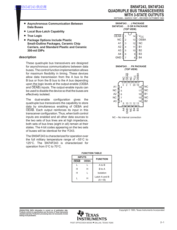
Page 1 Text Content
查询SN54F243 供应商 SN54F243, SN74F243
QUADRUPLE BUS TRANSCEIVERS
WITH 3-STATE OUTPUTS SDFS086 – MARCH 1987 – REVISED OCTOBER 1993 Asynchronous Communication Between SN54F243 J PACKAGE
SN74F243 D OR N PACKAGE
Data Buses
(TOP VIEW)
Local Bus-Latch Capability True Logic OEAB VCC
Package Options Include Plastic NC OEBA Small-Outline Packages, Ceramic Chip A1 NC Carriers, and Standard Plastic and Ceramic A2 B1 300-mil DIPs A3 B2 A4 B3
description GND B4
These quadruple bus transceivers are designed
for asynchronous communications between data SN54F243 FK PACKAGE (TOP VIEW)
buses. The control function implementation allows for maximum flexibility in timing. These devices allow data transmission from the A bus to the B bus or from the B bus to the A bus depending upon the logic levels at the output-enable (OEBA
A1 NC
and OEAB) inputs. The output-enable inputs can
be used to disable the device so that the buses are NC NC effectively isolated. A2 B1 NC NC
The dual-enable configuration gives the
quadruple bus transceivers the capability to store data by simultaneous enabling of OEBA and OEAB. Each output reinforces its input in this transceiver configuration. Thus, when both control inputs are enabled and all other data sources to NC – No internal connection the two sets of bus lines are at high impedance, both sets of bus lines (eight in all) remain at their states. The 4-bit codes appearing on the two sets of buses will be identical for the ′F243. The SN54F243 is characterized for operation over the full military temperature range of –55°C to 125°C. The SN74F243 is characterized for operation from 0°C to 70°C.
FUNCTION TABLE INPUTS
FUNCTION
OEAB OEBA
A to B B to A Isolation Latch A and B (A = B)
PRODUCTION DATA information is current as of publication date. Copyright 1993, Texas Instruments Incorporated
Products conform to specifications per the terms of Texas Instruments standard warranty. Production processing does not necessarily include testing of all parameters.
2–1POST OFFICE BOX 655303 • DALLAS, TEXAS 75265
Page Summary Contents For Texas Instruments SN54F243, SN74F243 Quadruple Bus Transceivers with 3-State Outputs
Manual Details
| Brand | Texas Instruments |
|---|---|
| Pages | 5 |
| File Size | 64.02 KB |
| Published | June 05, 2026 |
Enter the captcha to get the download link:

Frequently Asked Questions
How can I isolate the data buses using this transceiver?
You can use the output-enable inputs (OEBA and OEAB) to disable the device, effectively isolating the buses.
What are the operational temperature ranges for SN54F243 and SN74F243?
SN54F243 operates over the full military range (-55°C to 125°C), while SN74F243 operates from 0°C to 70°C.
How does this device allow data storage or latching?
The dual-enable configuration allows the transceiver to store data by simultaneously enabling both OEBA and OEAB inputs.
What voltage ranges are specified for the supply and input voltages?
The recommended operating input voltage range (VCC) is 4.5V to 5.5V, and the overall supply voltage range is –0.5V to 7V.