TEXAS INSTRUMENTS SN54ABT16646, SN74ABT16646 - 16-BIT BUS TRANSCEIVERS AND REGISTERS WITH 3-STATE OUTPUTS USER MANUAL
Summary
This robust 16-bit Bush Transceiver and Register provides high-speed, managed data transfer capability for complex digital systems. The device efficiently handles input bus data through D-type flip-flops, controlling operations like real-time transmission or isolation mode. The technical manual details essential features, including various operating modes, optimized pin configurations, physical package options (WD, DL, DGG), and reliable performance across wide temperature ranges. It is designed for engineers constructing circuits that require advanced bus management and robust data multiplexing capabilities.
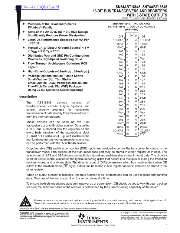
Page 1 Text Content
查询5962-9450201QXA供应商 SN54ABT16646, SN74ABT16646
16-BIT BUS TRANSCEIVERS AND REGISTERS
WITH 3-STATE OUTPUTS SCBS212D – JUNE 1992 – REVISED JULY 1999
Members of the Texas Instruments SN54ABT16646 WD PACKAGE SN74ABT16646 DGG OR DL PACKAGE
Widebus Family
(TOP VIEW)
State-of-the-Art EPIC-ΙΙB Bi CMOS Design Significantly Reduces Power Dissipation
1DIR 1OE
Latch-Up Performance Exceeds 500 m A Per 1CLKAB 1CLKBA JESD 17 1SAB 1SBA
Typical VOLP (Output Ground Bounce) < 1 V GND GND at VCC = 5 V, TA = 25°C 1A1 1B1 1A2 1B2
Distributed VCC and GND Pin Configuration
VCC VCC
Minimizes High-Speed Switching Noise
Flow-Through Architecture Optimizes PCB
Layout
High-Drive Outputs (–32-m A IOH, 64-m A IOL)
GND GND
Package Options Include Plastic Shrink 1A6 1B6 Small-Outline (DL), Thin Shrink 1A7 1B7 Small-Outline (DGG) Packages and 380-mil 1A8 1B8 Fine-Pitch Ceramic Flat (WD) Package
Using 25-mil Center-to-Center Spacings
description
GND GND 2A4 2B4
The ’ABT16646 devices consist of
bus-transceiver circuits, D-type flip-flops, and
control circuitry arranged for multiplexed
VCC VCC
transmission of data directly from the input bus or
from the internal registers. 2A7 2B7 2A8 2B8
These devices can be used as two 8-bit
GND GND
transceivers or one 16-bit transceiver. Data on the
2SAB 2SBA
A or B bus is clocked into the registers on the
2CLKAB 2CLKBA
low-to-high transition of the appropriate clock
2DIR 2OE
(CLKAB or CLKBA) input. Figure 1 illustrates the four fundamental bus-management functions that can be performed with the ’ABT16646 devices. Output-enable (OE) and direction-control (DIR) inputs are provided to control the transceiver functions. In the transceiver mode, data present at the high-impedance port may be stored in either register or in both. The select-control (SAB and SBA) inputs can multiplex stored and real-time (transparent mode) data. The circuitry used for select control eliminates the typical decoding glitch that occurs in a multiplexer during the transition between stored and real-time data. The direction control (DIR) determines which bus receives data when OE is low. In the isolation mode (OE high), A data can be stored in one register and/or B data can be stored in the other register. When an output function is disabled, the input function is still enabled and can be used to store and transmit data. Only one of the two buses, A or B, can be driven at a time. To ensure the high-impedance state during power up or power down, OE should be tied to VCC through a pullup resistor; the minimum value of the resistor is determined by the current-sinking capability of the driver.
Please be aware that an important notice concerning availability, standard warranty, and use in critical applications of Texas Instruments semiconductor products and disclaimers thereto appears at the end of this data sheet.
Widebus and EPIC-ΙΙB are trademarks of Texas Instruments Incorporated.
Copyright 1999, Texas Instruments Incorporated PRODUCTION DATA information is current as of publication date.
Products conform to specifications per the terms of Texas Instruments On products compliant to MIL-PRF-38535, all parameters are tested standard warranty. Production processing does not necessarily include unless otherwise noted. On all other products, production testing of all parameters. processing does not necessarily include testing of all parameters.
1POST OFFICE BOX 655303 • DALLAS, TEXAS 75265
Page Summary Contents For TEXAS INSTRUMENTS SN54ABT16646, SN74ABT16646 - 16-BIT BUS TRANSCEIVERS AND REGISTERS WITH 3-STATE OUTPUTS USER MANUAL
Manual Details
| Brand | Texas Instruments |
|---|---|
| Pages | 15 |
| File Size | 234.74 KB |
| Published | June 18, 2026 |
Enter the captcha to get the download link:

Frequently Asked Questions
How should the OE input be secured during power down?
To ensure a high-impedance state, the OE pin must be tied to V through a pullup capacitor resistor.
What does the Select-control input (SAB/SBA) enable?
It multiplexes stored and real-time data while eliminating typical decoding glitches that occur in standard multiplexers.
What is the SN54ABT16646's optimal temperature range?
The device is characterized for operation over the full military temperature range of –55°C to 125°C.