Texas Instruments CDC921 133-MHz Clock Synthesizer Driver for PCs with 3-State Output Motherboards
Summary
This advanced clock synthesizer/driver is essential hardware designed to generate precise, reliable system clock signals for PC motherboards supporting Pentium III class microprocessors. It synthesizes key frequencies—including CPU, PCI, and APIC—from a crystal input while ensuring low skew and low jitter performance. The accompanying technical documentation provides comprehensive details on variable frequency selection (100/133 MHz), 3-state output control, power management features, and electrical specifications for system architects and board design engineers integrating complex clocking solutions.
Page 1 Text Content
查询CDC921DL供应商 CDC921
133-MHz CLOCK SYNTHESIZER/DRIVER FOR PC MOTHERBOARDS
WITH 3-STATE OUTPUTS SCAS623 –MAY 27, 1999 Generates Clocks for Pentium III Class DL PACKAGE (TOP VIEW)
Microprocessors Supports a Single Pentium III
REF0 GND
Microprocessor
REF1 VDD2.5V
Uses a 14.318 MHz Crystal Input to
VDD3.3V APIC
Generate Multiple Output Frequencies
XIN GND
Includes Spread Spectrum Clocking (SSC),
XOUT VDD2.5V
0.5% Downspread for Reduced EMI
GND CPU_DIV2
Performance
PCI0 GND
Power Management Control Terminals PCI1 VDD2.5V
Low Output Skew and Jitter for Clock VDD3.3V CPU2 Distribution PCI2 GND PCI3 VDD2.5V
Operates from Dual 2.5-V and 3.3-V
PCI4 CPU1
Supplies
PCI5 CPU0
Generates the Following Clocks:
GND GND
– 3 CPU (2.5 V, 100/133 MHz)
PCI6 VDD3.3V
– 10 PCI (3.3 V, 33.3 MHz)
PCI7 GND
– 1 CPU/2 (2.5 V, 50/66 MHz)
VDD3.3V PWR_DWN
– 1 APIC (2.5 V, 16.67 MHz)
PCI8 SPREAD
– 3 3V66 (3.3 V, 66 MHz)
PCI9 SEL1
– 2 REF (3.3 V, 14.318 MHz)
GND SEL0
– 1 48MHz (3.3 V, 48 MHz)
3V66(0) VDD3.3V
Packaged in 48-Pin SSOP Package
3V66(1) 48MHz
Designed for Use with TI’s Direct Rambus
3V66(2) GND
Clock Generators (CDCR81, CDCR82,
VDD3.3V SEL133/100
CDCR83)
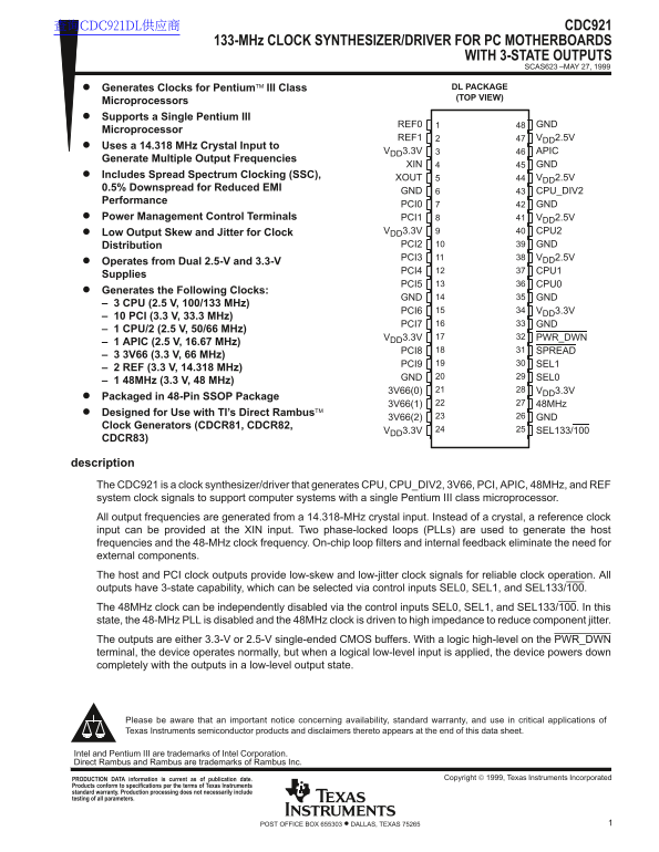
description The CDC921 is a clock synthesizer/driver that generates CPU, CPU_DIV2, 3V66, PCI, APIC, 48MHz, and REF system clock signals to support computer systems with a single Pentium III class microprocessor. All output frequencies are generated from a 14.318-MHz crystal input. Instead of a crystal, a reference clock input can be provided at the XIN input. Two phase-locked loops (PLLs) are used to generate the host frequencies and the 48-MHz clock frequency. On-chip loop filters and internal feedback eliminate the need for external components. The host and PCI clock outputs provide low-skew and low-jitter clock signals for reliable clock operation. All outputs have 3-state capability, which can be selected via control inputs SEL0, SEL1, and SEL133/100. The 48MHz clock can be independently disabled via the control inputs SEL0, SEL1, and SEL133/100. In this state, the 48-MHz PLL is disabled and the 48MHz clock is driven to high impedance to reduce component jitter. The outputs are either 3.3-V or 2.5-V single-ended CMOS buffers. With a logic high-level on the PWR_DWN terminal, the device operates normally, but when a logical low-level input is applied, the device powers down completely with the outputs in a low-level output state.
Please be aware that an important notice concerning availability, standard warranty, and use in critical applications of Texas Instruments semiconductor products and disclaimers thereto appears at the end of this data sheet.
Intel and Pentium III are trademarks of Intel Corporation. Direct Rambus and Rambus are trademarks of Rambus Inc.
Copyright 1999, Texas Instruments Incorporated PRODUCTION DATA information is current as of publication date.
Products conform to specifications per the terms of Texas Instruments standard warranty. Production processing does not necessarily include testing of all parameters.
1POST OFFICE BOX 655303 • DALLAS, TEXAS 75265
Page Summary Contents For Texas Instruments CDC921 133-MHz Clock Synthesizer Driver for PCs with 3-State Output Motherboards
Manual Details
| Brand | Texas Instruments |
|---|---|
| Pages | 17 |
| File Size | 236.04 KB |
| Published | June 16, 2026 |
Enter the captcha to get the download link:

Frequently Asked Questions
What frequencies does the CDC921 generate?
Generates clocks for CPUs (100/133 MHz), PCI (33.3 MHz), APIC (16.67 MHz), REF (14.318 MHz), and 3V66 (66 MHz).
How is the CPU bus frequency selected?
Set the SEL133/100 control input: High selects 133 MHz, Low selects 100 MHz.
What happens during power-down mode?
A logical low on PWR_DWN powers down the device with outputs in a low-level state.
What voltage supplies does it operate with?
Dual 2.5-V and 3.3-V supplies: CPU outputs use 2.5V, PCI/3V66 use 3.3V.