SIEMENS BTS720L1 User Guide
Summary
This smart four-channel highside power switch is an integrated solid-state solution designed for switching 12V DC grounded loads, offering a reliable alternative to electromechanical relays. The unit provides comprehensive industrial protection, including overvoltage, undervoltage, overload, and short-circuit management, along with advanced monitoring features like open load detection. This documentation serves as a detailed technical guide, covering all electrical specifications, operating principles, block diagrams, and advanced diagnostic procedures required for seamless integration into demanding power circuit applications.
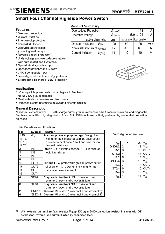
Page 1 Text Content
PROFET® BTS720L1
Smart Four Channel Highside Power Switch
Product Summary
Features
Overvoltage Protection Vbb(AZ)
• Overload protection
Operating voltage Vbb(on) 5.0 ... 24
• Current limitation
• Short-circuit protection active channels: one two parallel four parallel
• Thermal shutdown On-state resistance RON mΩ • Overvoltage protection
Nominal load current IL(NOM) 2.9 4.3 6.3
(including load dump)
Current limitation IL(SCr)
• Reverse battery protection1) • Undervoltage and overvoltage shutdown with auto-restart and hysteresis • Open drain diagnostic output • Open load detection in ON-state • CMOS compatible input • Loss of ground and loss of Vbb protection • Electrostatic discharge (ESD) protection
Application • µC compatible power switch with diagnostic feedback for 12 V DC grounded loads • Most suitable for resistive and lamp loads • Replaces electromechanical relays and discrete circuits
General Description N channel vertical power FET with charge pump, ground referenced CMOS compatible input and diagnostic feedback, monolithically integrated in Smart SIPMOS technology. Fully protected by embedded protection functions.
Pin Definitions and Functions Pin Symbol Function
Pin configuration (top view)
1,10, Vbb Positive power supply voltage. Design the 11,12, wiring for the simultaneous max. short circuit 15,16, currents from channel 1 to 4 and also for low
Vbb 1 • Vbb
19,20 thermal resistance
GND1/2 Vbb
IN1 Input 1 .. 4, activates channel 1 .. 4 in case of
IN1 OUT1
IN2 logic high signal
ST1/2 OUT2
IN2 Vbb
GND3/4 Vbb
OUT1 Output 1 .. 4, protected high-side power output
IN3 OUT3
OUT2 of channel 1 .. 4. Design the wiring for the
ST3/4 OUT4
OUT3 max. short circuit current
IN4 Vbb
Vbb Vbb
ST1/2 Diagnostic feedback 1/2 of channel 1 and
channel 2, open drain, low on failure
ST3/4 Diagnostic feedback 3/4 of channel 3 and
channel 4, open drain, low on failure
GND1/2 Ground 1/2 of chip 1 (channel 1 and channel 2) GND3/4 Ground 3/4 of chip 2 (channel 3 and channel 4)
1) With external current limit (e.g. resistor RGND=150 Ω) in GND connection, resistor in series with ST connection, reverse load current limited by connected load.
Semiconductor Group Page 1 of 14 26.Feb.96
Page Summary Contents For SIEMENS BTS720L1 User Guide
Manual Details
| Brand | Siemens |
|---|---|
| Pages | 14 |
| File Size | 382.93 KB |
| Published | May 31, 2026 |
Enter the captcha to get the download link:

Frequently Asked Questions
该开关的最大短路电流是多少?
最大的典型短路电流 (I_L(SC)) 是 18 A。
使用这个开关时,哪些负载类型是最佳选择?
它最适用于电阻性和灯泡负载。
如何检测通道是否发生开路故障?
通过诊断反馈引脚 (ST) 进行实时监测,出现故障时信号会变为低电平。
该设备的整体工作温度范围内是什么?
其操作温度范围为 -40°C 至 +150°C。