Siemens BTS 730 User Guide
Summary
This highly reliable PWM Power Unit provides precise, continuous power control for various loads, including LEDs or inductive systems. The comprehensive technical manual details its advanced features, ensuring system safety and performance optimization. Key protective mechanisms include integrated short circuit, overload, overtemperature, undervoltage, and load dump protection. It is designed for specialized engineers and hardware designers who require high-performance, robust power management solutions with adjustable switching frequency in demanding applications.
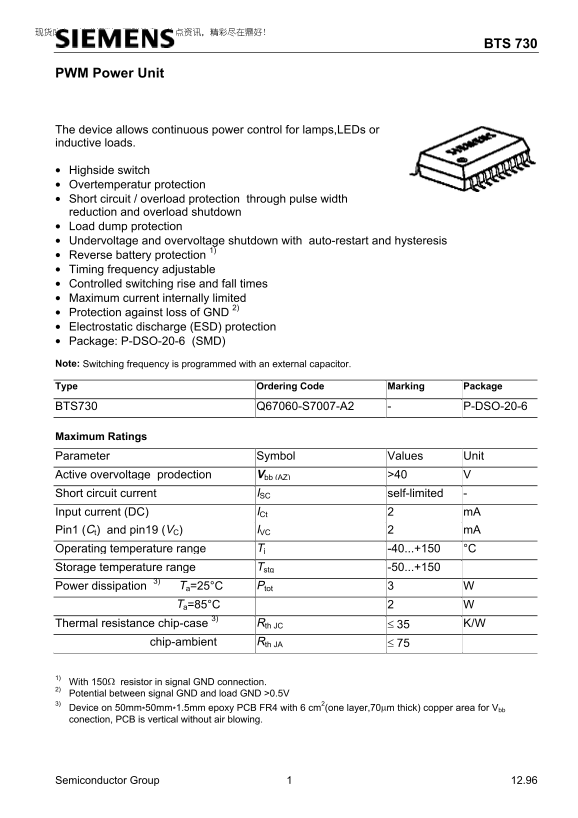
Page 1 Text Content
BTS 730
PWM Power Unit
The device allows continuous power control for lamps,LEDs or inductive loads.
• Highside switch • Overtemperatur protection • Short circuit / overload protection through pulse width reduction and overload shutdown • Load dump protection • Undervoltage and overvoltage shutdown with auto-restart and hysteresis • Reverse battery protection 1) • Timing frequency adjustable • Controlled switching rise and fall times • Maximum current internally limited • Protection against loss of GND 2) • Electrostatic discharge (ESD) protection • Package: P-DSO-20-6 (SMD) Note: Switching frequency is programmed with an external capacitor. Type Ordering Code Marking Package BTS730 Q67060-S7007-A2 P-DSO-20-6
Maximum Ratings Parameter Symbol Values Unit
Active overvoltage prodection Vbb (AZ) >40 Short circuit current ISC self-limited Input current (DC) ICt m A Pin1 (Ct) and pin19 (VC) IVC m A Operating temperature range Tj -40...+150 °C Storage temperature range Tstg -50...+150 Power dissipation 3) Ta=25°C Ptot
Ta=85°C
Thermal resistance chip-case 3) Rth JC ≤ 35 K/W chip-ambient Rth JA ≤ 75
1) With 150Ω resistor in signal GND connection. 2) Potential between signal GND and load GND >0.5V 3) Device on 50mm*50mm*1.5mm epoxy PCB FR4 with 6 cm2(one layer,70µm thick) copper area for Vbb conection, PCB is vertical without air blowing.
Semiconductor Group 12.96
Page Summary Contents For Siemens BTS 730 User Guide
Manual Details
| Brand | Siemens |
|---|---|
| Pages | 7 |
| File Size | 68.70 KB |
| Published | June 01, 2026 |
Enter the captcha to get the download link:

Frequently Asked Questions
What voltage range is required to activate overvoltage shutdown?
If the input battery voltage drops below 4.2 V bb, undervoltage shutdown activates.
How does the device protect against short circuits and overloads?
It uses pulse width reduction and implements an overload shutdown feature for protection.
What is the recommended PCB setup for operation?
Use a 50mm x 50mm, 1.5mm epoxy PCB FR4 with a 6 cm copper area for V bb connection.
How can I adjust the PWM switching frequency?
The switching frequency must be programmed using an external capacitor connected to pin C (pin 1).
What is the maximum rated output current limit?
The device has a load current limit of -20 A at room temperature and 3A when specified with L.