Siemens BTS 726 L1 User's Guide
Summary
The BTS 726 L1 is a smart, dual-channel highside power switch designed for reliable control of DC grounded loads in 12V and 24V systems. This integrated solution simplifies circuit design by replacing complex electromechanical relays and discrete components. The manual provides comprehensive technical details on using this robust N-channel FET, detailing its advanced protective features, including overvoltage, undervoltage, overload, short-circuit protection, and open load detection in both ON and OFF states. It is essential reading for electrical engineers and power electronics designers requiring high-reliability switching for resistive, inductive, and capacitive loads.
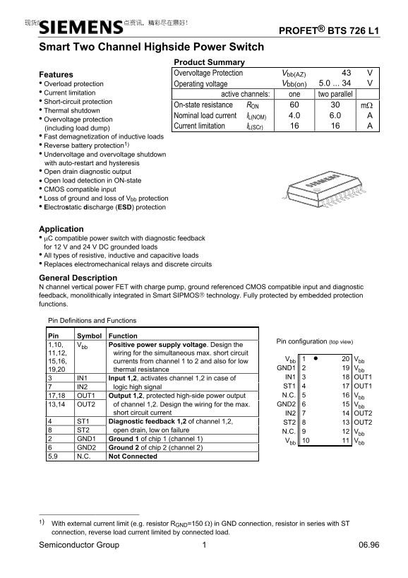
Page 1 Text Content
PROFET® BTS 726 L1
Smart Two Channel Highside Power Switch
Product Summary Features Overvoltage Protection Vbb(AZ)
• Overload protection Vbb(on) 5.0 ... 34
Operating voltage
• Current limitation
active channels: one two parallel
• Short-circuit protection
On-state resistance RON mΩ
• Thermal shutdown
Nominal load current IL(NOM) 4.0 6.0
• Overvoltage protection
Current limitation IL(SCr)
(including load dump) • Fast demagnetization of inductive loads • Reverse battery protection1) • Undervoltage and overvoltage shutdown with auto-restart and hysteresis • Open drain diagnostic output • Open load detection in ON-state • CMOS compatible input • Loss of ground and loss of Vbb protection • Electrostatic discharge (ESD) protection
Application • µC compatible power switch with diagnostic feedback for 12 V and 24 V DC grounded loads • All types of resistive, inductive and capacitive loads • Replaces electromechanical relays and discrete circuits
General Description N channel vertical power FET with charge pump, ground referenced CMOS compatible input and diagnostic feedback, monolithically integrated in Smart SIPMOS technology. Fully protected by embedded protection functions.
Pin Definitions and Functions
Pin Symbol Function
Pin configuration (top view)
1,10, Vbb Positive power supply voltage. Design the 11,12, wiring for the simultaneous max. short circuit
Vbb 1 • Vbb
15,16, currents from channel 1 to 2 and also for low
19,20 thermal resistance GND1 Vbb IN1 Input 1,2, activates channel 1,2 in case of IN1 OUT1 IN2 logic high signal ST1 OUT1 17,18 OUT1 Output 1,2, protected high-side power output N.C. Vbb 13,14 OUT2 of channel 1,2. Design the wiring for the max. GND2 Vbb
short circuit current IN2 OUT2
ST1 Diagnostic feedback 1,2 of channel 1,2, ST2 OUT2 ST2 open drain, low on failure N.C. Vbb GND1 Ground 1 of chip 1 (channel 1)
Vbb Vbb
GND2 Ground 2 of chip 2 (channel 2)
5,9 N.C. Not Connected
1) With external current limit (e.g. resistor RGND=150 Ω) in GND connection, resistor in series with ST connection, reverse load current limited by connected load.
Semiconductor Group 06.96
Page Summary Contents For Siemens BTS 726 L1 User's Guide
Manual Details
| Brand | Siemens |
|---|---|
| Pages | 15 |
| File Size | 204.31 KB |
| Published | June 01, 2026 |
Enter the captcha to get the download link:

Frequently Asked Questions
What is the maximum supply voltage (V)?
The maximum overvoltage protection rating is 43 V bb.
Does this device support various types of loads?
Yes, it supports all types of resistive, inductive, and capacitive loads.
How does Overload protection work?
It has an operating voltage range/current limitation described by the nominal load current (I_L(NOM)) up to 6.0 A.
What special features are available for monitoring fault conditions?
It provides open drain diagnostic output and supports open load detection in the ON-state.