# A B C D E F G H I J K L M N O P Q R S T U V W X Y Z

Siemens BTS 933 User Guide and Manual

Summary

This smart lowside power switch is an advanced N-channel FET solution designed to replace traditional electromechanical relays and discrete circuitry in 12V or 24V DC applications. It offers comprehensive, embedded protection against common faults such as thermal overload, overvoltage, short circuits, and current limits. This technical guide provides engineers and hardware designers with detailed electrical characteristics, operational guidelines, and specifications required to reliably integrate the BTS 933 into demanding resistive, inductive, or capacitive load switching systems.
📄 Preview PAGE OF 11

Page 1 Text Content

HITFETBTS 933

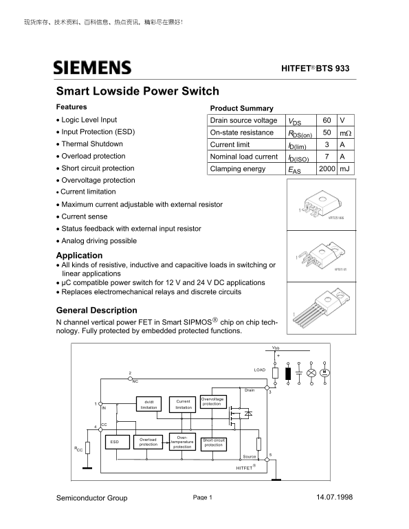
Smart Lowside Power Switch Features Product Summary • Logic Level Input Drain source voltage V60VDS • Input Protection (ESD) On-state resistance RDS(on) mΩ • Thermal Shutdown ID(lim) ACurrent limit • Overload protection Nominal load current AID(ISO) • Short circuit protection Clamping energy m JEAS • Overvoltage protection • Current limitation • Maximum current adjustable with external resistor • Current sense • Status feedback with external input resistor • Analog driving possible

Application • All kinds of resistive, inductive and capacitive loads in switching or linear applications • µC compatible power switch for 12 V and 24 V DC applications • Replaces electromechanical relays and discrete circuits

General Description N channel vertical power FET in Smart SIPMOS chip on chip tech- nology. Fully protected by embedded protected functions.

Drain

Overvoltage

dv/dt Current

protection

IN limitation limitation

Over-

Overload

ESD temperature Short circuit

protection

protection protection

Source

HITFET

14.07.1998Semiconductor Group

Page Summary Contents For Siemens BTS 933 User Guide and Manual

Page 1 HITFETBTS 933 Smart Lowside Power Switch Features Product Summary • Logic Level Input Drain source voltage V60VDS • Input Protection (ESD) On-state resistance RDS(on) mΩ • Thermal Shutdown ID(lim) AC...
Page 2 BTS 933 Maximum Ratings at Tj = 25 °C unless otherwise specified Parameter Symbol Unit Value Drain source voltage VDS VDS(SC) Drain source voltage for short circuit protection RCC = 0 Ω without RCC Co...
Page 3 BTS 933 Electrical Characteristics Parameter Symbol Unit Values max.typ.min.at Tj=25°C, unless otherwise specified Characteristics -Drain source clamp voltage VVDS(AZ) Tj = - 40 ...+ 150°C, ID = 10 m ...
Page 4 BTS 933 Electrical Characteristics Parameter Symbol Values Unit at Tj=25°C, unless otherwise specified min. typ. max. Characteristics Initial peak short circuit current limit ID(SCp) VIN = 10 V, VDS =...
Page 5 BTS 933 Block Diagramm Terms Inductive and overvoltage output clamp ID Vbb HITFET IN CC HITFET Short circuit behaviour The ground lead impedance of RCC should be as low as possible Input circuit (ESD ...
Page 6 BTS 933 On-state resistance Maximum allowable power dissipation RON = f(Tj); ID=7A; VIN=10V Ptot = f(Tc) BTS 933 RDS(on) On-state resistance Typ. input threshold voltage RON = f(Tj); ID= 7A; VIN=5V VI...
Page 7 BTS 933 Typ. transfer characteristics Typ. short circuit current ID = f(VIN); VDS=12V; Tj=25°C IDlim = f(Tj); RCC=0Ω, VDS=12V Parameter: VIN ID ID 10V VIN Tj Typ. output characteristic Safe Operating ...
Page 8 BTS 933 Typ. current limit versus RCC Typ. current sense characteristics ID(lim) = f(RCC); Tj=25°C VCC = f(ID); VIN=10V Parameter: VIN Parameter: RCC, Tj 56 Ohm 22 Ohm no Rcc 10 Ohm Transient thermal ...
Page 9 BTS 933 Application examples: Current Sense Features and Status Signals IN HITFET µC Vbb RCCVCC thermal shutdown reached triptemperature The accuray of Vcc is at each temperature about ±10 % Status si...
Page 10 BTS 933 Package and ordering code all dimensions in mm Ordering code: Q67060-S6701-A4 Ordering Code: Q67060-S6701-A2 Ordering Code: Q67060-S6701-A3 14.07.1998Semiconductor Group
Page 11 BTS 933 Edition 7.97 Published by Siemens AG, Bereich Halbleiter Vetrieb, Werbung, Balanstraße 73, 81541 München © Siemens AG 1997 All Rights Reserved. Attention please! As far as patents or other rig...