Siemens BTS 728 L2 User Guide and Manual
Summary
The PROFET BTS 728 L2 is a dual-channel smart high-side power switch MOSFET designed for robust, microcontroller-compatible load control. This advanced component features integrated diagnostic capabilities, including open/short circuit detection, overload protection, and thermal shutdown, making it ideal for replacing traditional relays and discrete circuits in systems ranging from low-voltage to 24V loads. The comprehensive manual provides detailed technical specifications, functional diagrams, maximum ratings, and wiring guides for engineers designing reliable power switching solutions that handle inductive, resistive, and capacitive loads while ensuring system longevity.
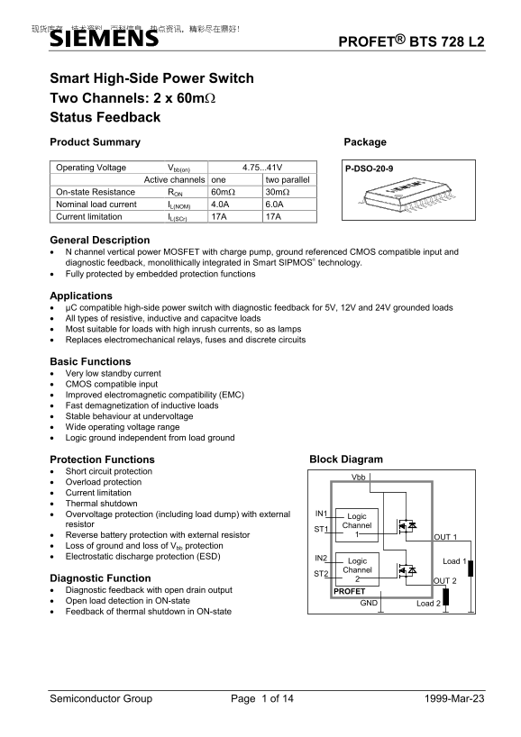
Page 1 Text Content
PROFET® BTS 728 L2
Smart High-Side Power Switch Two Channels: 2 x 60mΩ Status Feedback Product Summary Package Operating Voltage Vbb(on) 4.75...41V P-DSO-20-9
Active channels one two parallel
On-state Resistance RON 60mΩ 30mΩ Nominal load current IL(NOM) 4.0A 6.0A Current limitation IL(SCr) 17A 17A
General Description • N channel vertical power MOSFET with charge pump, ground referenced CMOS compatible input and diagnostic feedback, monolithically integrated in Smart SIPMOS technology. • Fully protected by embedded protection functions
Applications • µC compatible high-side power switch with diagnostic feedback for 5V, 12V and 24V grounded loads • All types of resistive, inductive and capacitve loads • Most suitable for loads with high inrush currents, so as lamps • Replaces electromechanical relays, fuses and discrete circuits
Basic Functions • Very low standby current • CMOS compatible input • Improved electromagnetic compatibility (EMC) • Fast demagnetization of inductive loads • Stable behaviour at undervoltage • Wide operating voltage range • Logic ground independent from load ground
Protection Functions Block Diagram
• Short circuit protection
• Overload protection • Current limitation • Thermal shutdown
• Overvoltage protection (including load dump) with external IN1
Logic
resistor Channel
• Reverse battery protection with external resistor
OUT 1
• Loss of ground and loss of Vbb protection • Electrostatic discharge protection (ESD) IN2
Logic Load 1 Channel
Diagnostic Function
OUT 2
• Diagnostic feedback with open drain output PROFET • Open load detection in ON-state
GND Load 2
• Feedback of thermal shutdown in ON-state
Semiconductor Group Page 1 of 14 1999-Mar-23
Page Summary Contents For Siemens BTS 728 L2 User Guide and Manual
Manual Details
| Brand | Siemens |
|---|---|
| Pages | 14 |
| File Size | 267.58 KB |
| Published | May 31, 2026 |
Enter the captcha to get the download link:

Frequently Asked Questions
What types of electrical loads are compatible with this power switch?
It can handle all types of resistive, inductive, and capacitive loads.
Does the PROFET BTS 728 L2 include built-in protective functions?
Yes, it includes multiple protections such as short circuit protection, overload protection, and current limitation.
What is the maximum rated operating temperature range for the device?
The specified operational temperature range is from -40°C to +150°C.
What material and minimum size PCB is recommended for proper use?
It should be mounted on a 50mm*50mm*1.5mm epoxy PCB FR4, which must provide at least a 6cm copper area.