ROHM US6M1 User Guide
Summary
The US6M1 is a dual N-channel/P-channel MOSFET transistor designed for efficient power switching and DC/DC converter applications. Featuring low on-resistance, a small surface mount package, and integrated gate protection, it ensures reliable performance in demanding high-power circuits. This comprehensive manual provides detailed electrical specifications, absolute maximum ratings, and technical transfer curves, making it the essential resource for engineers designing advanced power electronics systems.
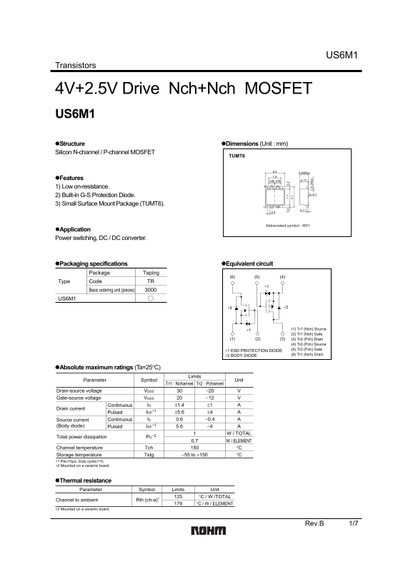
Page 1 Text Content
US6M1
Transistors
4V+2.5V Drive Nch+Nch MOSFET US6M1 Structure Dimensions (Unit : mm) Silicon N-channel / P-channel MOSFET
TUMT6
Features 1) Low on-resistance. 2) Built-in G-S Protection Diode. 3) Small Surface Mount Package (TUMT6).
Abbreviated symbol : M01
Application Power switching, DC / DC converter.
Packaging specifications Equivalent circuit
Package Taping
Type Code TR
Basic ordering unit (pieces)
US6M1
0. 2M ax
∗1 (1) Tr1 (Nch) Source (2) Tr1 (Nch) Gate
(1) (2) (3) (3) Tr2 (Pch) Drain
(4) Tr2 (Pch) Source (5) Tr2 (Pch) Gate
∗1 ESD PROTECTION DIODE
∗2 BODY DIODE (6) Tr1 (Nch) Drain
Absolute maximum ratings (Ta=25°C)
Limits
Parameter Symbol Unit
Tr1 : Nchannel Tr2 : Pchannel
Drain-source voltage VDSS −20 V30 Gate-source voltage VGSS −12 Continuous ID ±1.4 ±1
Drain current
∗1 Pulsed IDP ±5.6 ±4 Continuous Source current IS 0.6 −0.4 (Body diode) ∗1 Pulsed ISP 5.6 −4
W / TOTAL∗2
Total power dissipation PD
W / ELEMENT0.7 Channel temperature °CTch
Storage temperature −55 to +150 °CTstg
∗1 Pw≤10µs, Duty cycle≤1% ∗2 Mounted on a ceramic board.
Thermal resistance Parameter Symbol Limits Unit
°C / W /TOTAL
Channel to ambient Rth (ch-a)
°C / W / ELEMENT
∗2 Mounted on a ceramic board.
Rev.B 1/7
Page Summary Contents For ROHM US6M1 User Guide
Manual Details
| Brand | ROHM |
|---|---|
| Pages | 8 |
| File Size | 108.28 KB |
| Published | June 18, 2026 |
Enter the captcha to get the download link:

Frequently Asked Questions
What is the maximum permissible power dissipation (Pd)?
The maximum total power dissipation (TOTAL Pd) is 0.7 W / TOTAL.
Is this MOSFET built-in protection for ESD?
Yes, it features a built-in G-S Protection Diode.
Can these transistors be used in high-reliability life support equipment?
No, consult with the sales representative if use in critical safety machinery is required.
What are the key electrical limitations for drain current (Id)?
The continuous drain current limit (TOTAL I) for Tr1 (Nch) is 1.4 A, and there is a pulsed limit of up to ±5.6 A.