ROHM R5021ANX User Guide
Summary
This documentation provides comprehensive technical specifications for the R5021ANX N-channel MOSFET transistor, ideal for high-performance switching applications. Featuring low on-resistance and fast switching capabilities, this reliable component is designed for ease of integration into complex power circuits up to 500V. The manual details electrical characteristics, thermal performance, and operating curves, making it essential for electronics engineers designing robust DC motor drives, power converters, or general industrial switching equipment.
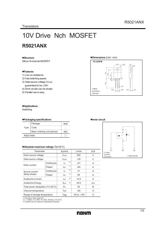
Page 1 Text Content
R5021ANX
Transistors
10V Drive Nch MOSFET R5021ANX
Structure Dimensions (Unit : mm)
Silicon N-channel MOSFET TO-220FM
Features 1) Low on-resistance.
2) Fast switching speed. 1.3 3) Gate-source voltage (VGSS) guaranteed to be 30V. 0.8
4) Drive circuits can be simple. (1)Base
2.54 0.75 2.62.54 (2)Collector (2) (3)(1)
5) Parallel use is easy.
(3)Emitter
Applications
Switching
Packaging specifications Inner circuit Package Bulk Type Code Basic ordering unit (pieces)
R5021ANX
Absolute maximum ratings (Ta=25 C)
Parameter Symbol Limits Unit
(1) Gate (2) Drain
Drain-source voltage VDSS ∗1 Body Diode
(3) Source
Gate-source voltage VGSS ±30
Continuous ±21ID
Drain current
Pulsed IDP A±84
Continuous
Source current
(Body Diode) ∗1
Pulsed ISP
Avalanche Current IAS 10.5
Avalanche Energy EAS ∗2 29.6 m J
Total power dissipation (Tc=25°C) PD
Channel temperature Tch °C
Range of storage temperature Tstg °C−55 to +150 ∗1 Pw≤10μs, Duty cycle≤1% ∗2 L 500μH, VDD=50V, RG=25Ω, Starting, Tch=25°C ∗3 Limited only by maximum temperature allowed
Page Summary Contents For ROHM R5021ANX User Guide
Manual Details
| Brand | ROHM |
|---|---|
| Pages | 6 |
| File Size | 232.32 KB |
| Published | May 31, 2026 |
Enter the captcha to get the download link:

Frequently Asked Questions
What is the minimum operational resistance (RDS(on))?
Under specified conditions, the static drain-source on-state resistance is 0.16 Ω.
How much power can this transistor dissipate at room temperature?
The total power dissipation Pd under normal conditions is limited to 50 W.
Are there any restrictions when using this device with critical safety equipment?
You must consult a sales representative if using it in devices requiring extremely high reliability, such as medical or aerospace machinery.
What are the specifications for parallel use?
The manual indicates that parallel use of the transistors is easy.