ROHM UMT2907A SST2907A MMST2907A User Guide
Summary
These PNP Medium Power Transistors are designed for reliable switching applications in various electronic circuits. This comprehensive technical manual provides engineers and designers with detailed data, including absolute maximum ratings, essential electrical characteristics, DC current gain ($h_{FE}$), saturation voltages, and frequency response curves. It covers performance parameters necessary for accurate circuit integration, making it an essential resource for professionals developing robust power control and switching systems.
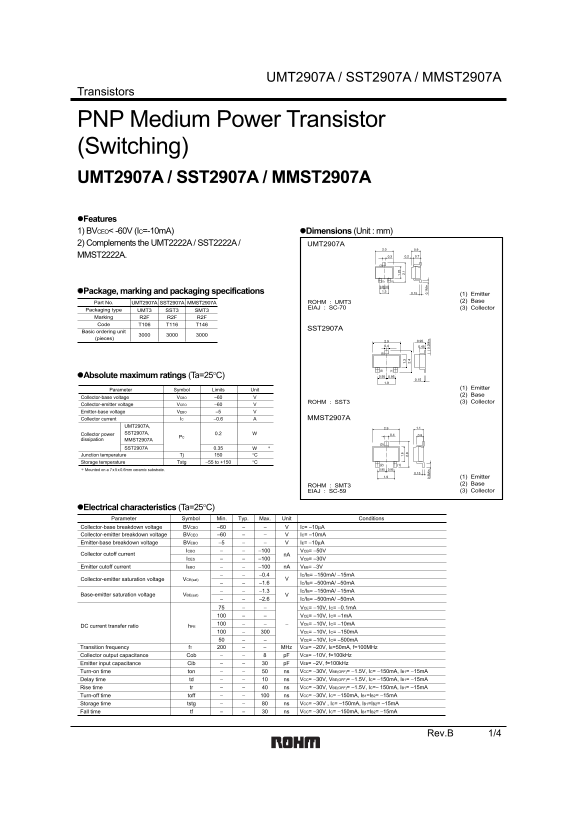
Page 1 Text Content
UMT2907A / SST2907A / MMST2907A
Transistors
PNP Medium Power Transistor (Switching) UMT2907A / SST2907A / MMST2907A Features 1) BVCEO< -60V (IC=-10m A) Dimensions (Unit : mm) 2) Complements the UMT2222A / SST2222A / UMT2907A MMST2222A.
Package, marking and packaging specifications
(1) Emitter Part No. UMT2907A SST2907A MMST2907A ROHM : UMT3 (2) Base
EIAJ : SC-70 (3) Collector
Packaging type UMT3 SST3 SMT3 Marking R2F R2F R2F Code T106 T116 T146
SST2907A
Basic ordering unit (pieces)
Absolute maximum ratings (Ta=25°C)
Parameter Symbol Limits Unit (1) Emitter (2) Base
Collector-base voltage VCBO −60
ROHM : SST3 (3) Collector
Collector-emitter voltage VCEO −60 Emitter-base voltage VEBO −5
Collector current IC −0.6 MMST2907A
UMT2907A, Collector power SST2907A, 0.2
dissipation MMST2907A
SST2907A 0.35
Junction temperature Tj °C
Storage temperature Tstg −55 to +150 °C
∗ Mounted on a 7 x 5 x 0.6mm ceramic substrate.
(1) Emitter ROHM : SMT3 (2) Base EIAJ : SC-59 (3) Collector
Electrical characteristics (Ta=25°C) Parameter Symbol Min. Typ. Max. Unit Conditions
Collector-base breakdown voltage BVCBO −60 IC= −10µA
Collector-emitter breakdown voltage BVCEO −60 IC= −10m A
Emitter-base breakdown voltage BVEBO −5 IE= −10µA ICBO −100 VCB= −50V
Collector cutoff current n A
ICES −100 VCB= −30V
Emitter cutoff current IEBO −100 n A VEB= −3V
−0.4 IC/IB= −150m A/ −15m A
Collector-emitter saturation voltage VCE(sat)
−1.6 IC/IB= −500m A/ −50m A
−1.3 IC/IB= −150m A/ −15m A
Base-emitter saturation voltage VBE(sat)
−2.6 IC/IB= −500m A/ −50m A
VCE= −10V, IC= −0.1m A VCE= −10V, IC= −1m A VCE= −10V, IC= −10m A
DC current transfer ratio h FE
VCE= −10V, IC= −150m A VCE= −10V, IC= −500m A Transition frequency f T MHz VCE= −20V, IE=50m A, f=100MHz Collector output capacitance Cob p F VCB= −10V, f=100k Hz Emitter input capacitance Cib p F VEB= −2V, f=100k Hz Turn-on time ton ns VCC= −30V, VBE(OFF)= −1.5V, IC= −150m A, IB1= −15m A Delay time td ns VCC= −30V, VBE(OFF)= −1.5V, IC= −150m A, IB1= −15m A Rise time ns VCC= −30V, VBE(OFF)= −1.5V, IC=− 150m A, IB1= −15m Atr Turn-off time ns VCC= −30V, IC= −150m A, IB1=IB2= −15m Atoff Storage time tstg ns VCC= −30V , IC= −150m A, IB1=IB2= −15m A Fall time ns VCC= −30V, IC= −150m A, IB1=IB2= −15m A tf
Rev.B 1/4
Page Summary Contents For ROHM UMT2907A SST2907A MMST2907A User Guide
Manual Details
| Brand | ROHM |
|---|---|
| Pages | 5 |
| File Size | 111.74 KB |
| Published | June 18, 2026 |
Enter the captcha to get the download link:

Frequently Asked Questions
What is the maximum continuous collector power dissipation?
The MMST2907A dissipates 0.35 W when mounted on a specific ceramic substrate.
What are the recommended usage limitations for critical equipment?
These components should not be used in devices that endanger human life (e.g., medical, aerospace machinery). Consult sales for such applications.
How is reliability enhanced during design?
Designers must consider derating characteristics and implement safety features like extra margin and fail-safe measures to prevent accidents.
What is the device's typical turn-on time (ton)?
The transition time indicates a typical on time (ton) of 50 ns under specified bias conditions.