ROHM UMF28N User Guide
Summary
Enhance your power management systems with the UMF28N, a dual-transistor consolidated package designed for highly efficient power switching circuits. This comprehensive manual provides essential documentation, including detailed electrical characteristics, performance curves, absolute maximum ratings, and physical specifications. It is an indispensable resource for electronics engineers and circuit designers building reliable, compact, and cost-effective electronic equipment requiring robust power control.
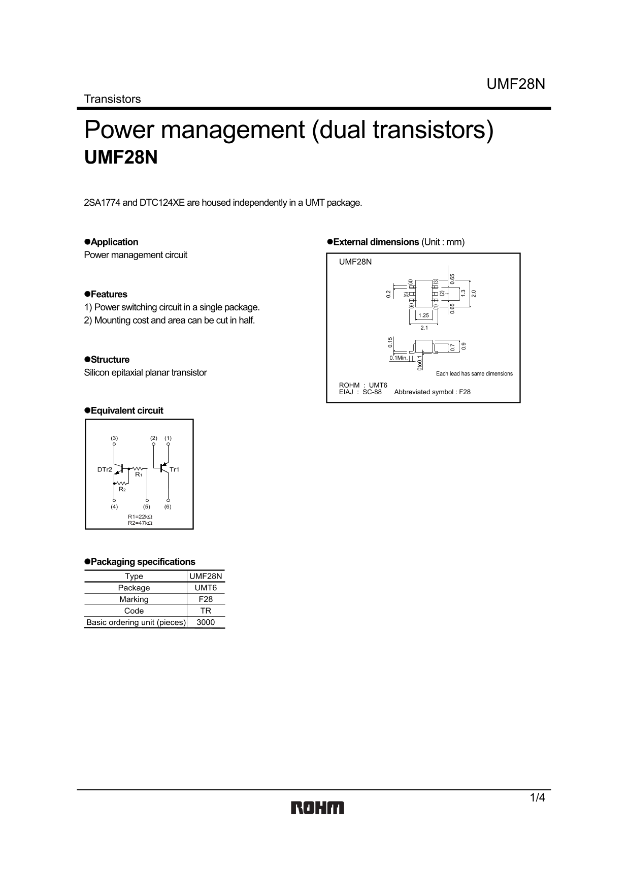
Page 1 Text Content
UMF28N
Transistors
Power management (dual transistors) UMF28N 2SA1774 and DTC124XE are housed independently in a UMT package.
Application External dimensions (Unit : mm) Power management circuit
UMF28N
Features 1) Power switching circuit in a single package.
2) Mounting cost and area can be cut in half.
0.1Min.
Structure Silicon epitaxial planar transistor Each lead has same dimensions
ROHM : UMT6
EIAJ : SC-88 Abbreviated symbol : F28
Equivalent circuit
DTr2 Tr1
Packaging specifications Type UMF28N
Package UMT6 Marking F28 Code TR
Basic ordering unit (pieces)
Page Summary Contents For ROHM UMF28N User Guide
Manual Details
| Brand | ROHM |
|---|---|
| Pages | 5 |
| File Size | 78.22 KB |
| Published | July 07, 2026 |
Enter the captcha to get the download link:

Frequently Asked Questions
Can this transistor be used in life-safety critical equipment?
The manual warns that users seeking extremely high reliability for devices like medical or aerospace machinery must consult a sales representative first.
What is the maximum specified operational temperature range?
For both Tr1 and DTr2, the junction temperature (Tj) and storage temperature (Tstg) limits are 150 °C.
How does using a single-package power switching circuit benefit design?
It allows mounting costs and required area to be potentially cut in half, while also integrating the necessary power switching function.
What types of ordinary electronic devices are these products intended for?
They are designed for typical equipment such as audio visual, office automation, communications devices, and standard electrical appliances.