ROHM RZR040P01 User Guide
Summary
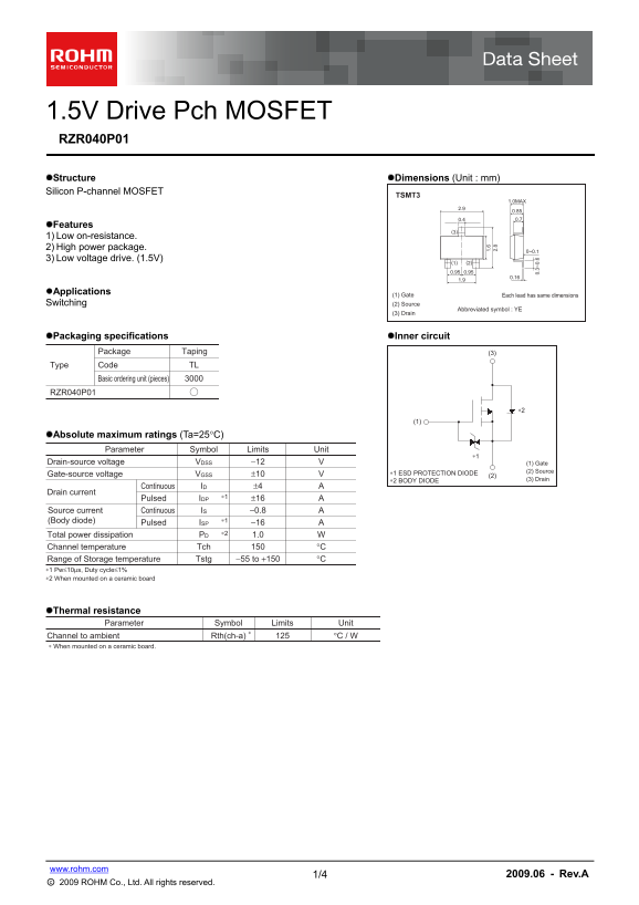
This technical guide details the specifications for a low-voltage drive P-channel MOSFET, ideal for power switching applications. The manual provides comprehensive data—including absolute maximum ratings, on-resistance characteristics ($R_{ds(on)}$), and timing diagrams—for engineers designing general-use electronic equipment. Features include high power handling in a robust package and efficient operation with only 1.5V gate drive voltage.
Page 1 Text Content
1.5V Drive Pch MOSFET RZR040P01 Structure Dimensions (Unit : mm) Silicon P-channel MOSFET
TSMT3
1.0MAX
Features
1) Low on-resistance. 2) High power package.
3) Low voltage drive. (1.5V)
Applications
Each lead has same dimensions(1) Gate
Switching (2) Source
Abbreviated symbol : YE
(3) Drain
Packaging specifications Inner circuit
Package Taping (3)
Type Code TL
Basic ordering unit (pieces)
RZR040P01
Absolute maximum ratings (Ta=25°C)
Parameter Symbol Limits Unit
Drain-source voltage −12 VVDSS (1) Gate
∗1 ESD PROTECTION DIODE (2) Source
Gate-source voltage ±10 VVGSS (2)
∗2 BODY DIODE (3) Drain
Continuous ±4 AID 1.
Drain current
Pulsed ±16 AIDP Source current Continuous −0.8 AIS
(Body diode) ∗1
Pulsed −16 AISP Total power dissipation ∗2 1.0 WPD
Channel temperature °CTch
Range of Storage temperature −55 to +150 °CTstg
∗1 Pw≤10µs, Duty cycle≤1% ∗2 When mounted on a ceramic board
Thermal resistance
Parameter Symbol Limits Unit
Channel to ambient 125∗ °C / WRth(ch-a) ∗ When mounted on a ceramic board.
1/4 www.rohm.com 2009.06 - Rev.A
○c 2009 ROHM Co., Ltd. All rights reserved.
Page Summary Contents For ROHM RZR040P01 User Guide
Manual Details
| Brand | ROHM |
|---|---|
| Pages | 5 |
| File Size | 218.15 KB |
| Published | June 15, 2026 |
Enter the captcha to get the download link:

Frequently Asked Questions
What is the maximum ambient temperature range for safe operation?
The storage temperature range (Tstg) is -55 to +150°C, with a channel operating temperature (Tch) of 150°C.
How do I find the voltage ratings for this MOSFET?
The absolute maximum rating specifies a drain-source voltage (VDS) limit of -12 V and supports gate-source voltages (VGSS) up to ±10 V.
What are the guidelines for implementing safety measures?
Users must implement safety measures like derating, redundancy, or fail-safe designs to guard against physical injury or fire upon failure.
What is the static on-state resistance at rated conditions?
The minimum type (Typ.) value for Drain-source on-state (RDS(on)) is 40 mΩ and maximum is 60 mΩ when ID = -2A and VGS = -1.8V.