ROHM RUF015N02 User Guide
Summary
Provides comprehensive technical specifications for the RUF015N02 Silicon N-channel MOSFET transistor, a space-saving component optimized for low on-resistance and 1.8V drive applications. This documentation is essential for electrical engineers and product designers building reliable electronic systems. It details critical performance graphs, including switching characteristics, leakage current limits, thermal resistance, and static drain-source curves, ensuring accurate implementation in circuits ranging from consumer electronics to industrial control equipment.
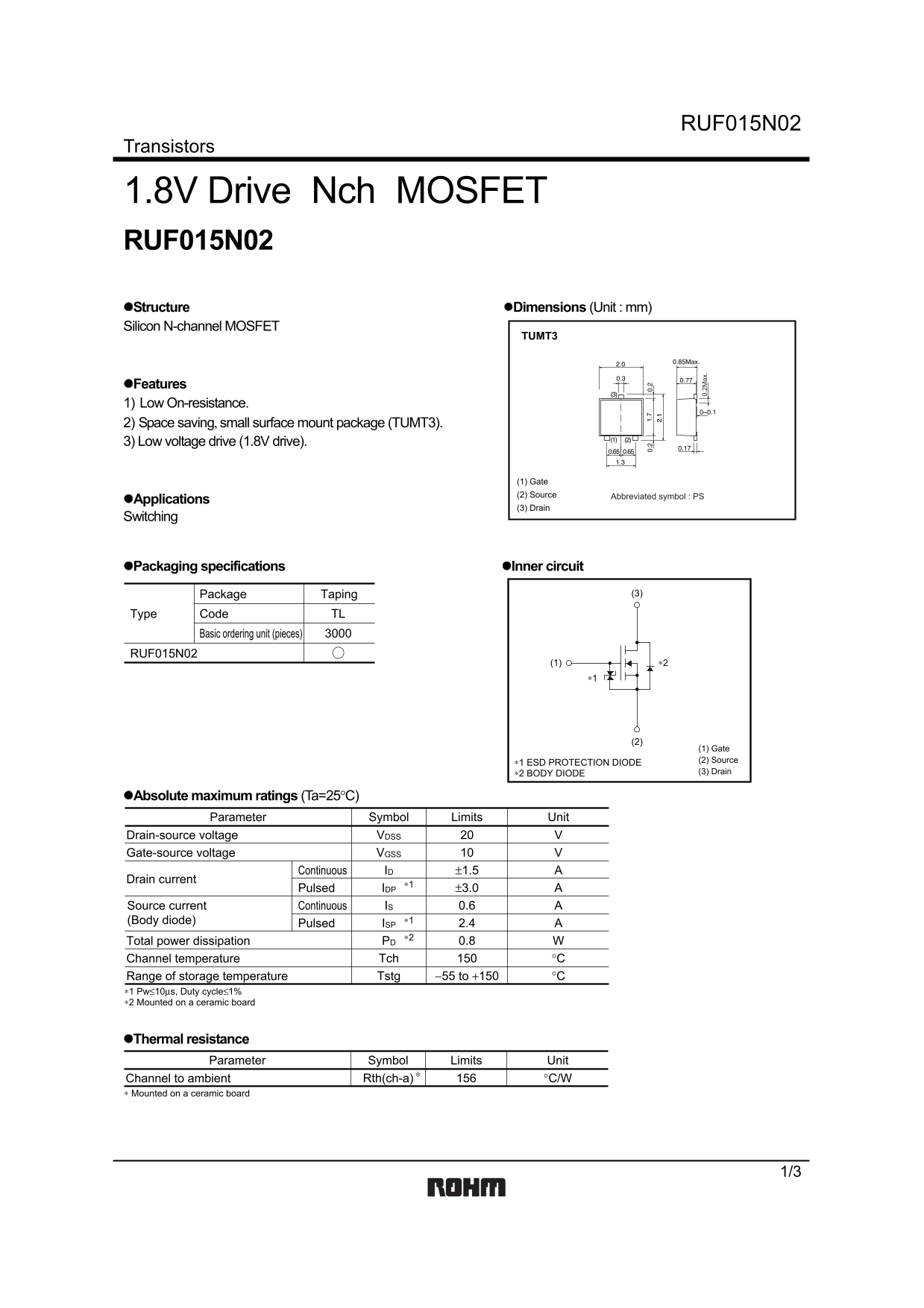
Page 1 Text Content
RUF015N02
Transistors
1.8V Drive Nch MOSFET RUF015N02 Structure Dimensions (Unit : mm) Silicon N-channel MOSFET
TUMT3
Features 1) Low On-resistance. 2) Space saving, small surface mount package (TUMT3). 3) Low voltage drive (1.8V drive).
(1) Gate (2) Source Abbreviated symbol : PS
Applications
(3) Drain
Switching
Packaging specifications Inner circuit
Package Taping (3)
Type Code TL
Basic ordering unit (pieces)
RUF015N02
0. 2M ax
(1) Gate ∗1 ESD PROTECTION DIODE (2) Source ∗2 BODY DIODE (3) Drain
Absolute maximum ratings (Ta=25°C)
Parameter Symbol Limits Unit
Drain-source voltage VVDSS Gate-source voltage VVGSS Continuous ±1.5 AID
Drain current
Pulsed ±3.0 AIDP Source current Continuous 0.6 AIS
(Body diode) ∗1
Pulsed 2.4 AISP
Total power dissipation 0.8 WPD Channel temperature °CTch Range of storage temperature −55 to +150 °CTstg
∗1 Pw≤10µs, Duty cycle≤1% ∗2 Mounted on a ceramic board
Thermal resistance
Parameter Symbol Limits Unit
Channel to ambient °C/WRth(ch-a)
∗ Mounted on a ceramic board
Page Summary Contents For ROHM RUF015N02 User Guide
Manual Details
| Brand | ROHM |
|---|---|
| Pages | 4 |
| File Size | 111.16 KB |
| Published | July 22, 2026 |
Enter the captcha to get the download link:

Frequently Asked Questions
Is ESD protection necessary when using this MOSFET?
Yes, the datasheet warns that the product might cause chip aging under an electrified environment, making it recommended to design an ESD protection circuit.
What is the maximum continuous drain current (ID) I can handle?
The maximum specified continuous Drain current (ID) limit for RUF015N02 is ±1.5 A.
What board type should be used when calculating thermal resistance?
The listed thermal resistance values specify that the component must be mounted on a ceramic board.
Can I use this MOSFET in high-reliability systems (e.g., medical equipment)?
If using it with life-safety devices, you must consult a sales representative and account for failure by integrating derating and fail-safe measures.