ROHM RHP020N06 User Guide
Summary
This N-channel Power MOSFET is designed for demanding high-speed switching applications, delivering low on-resistance and a wide Safe Operating Area (SOA). The accompanying manual serves as a technical deep dive, detailing crucial operational parameters such as absolute maximum ratings, transient electrical characteristics, thermal performance curves, and package specifications. This document is ideal for power electronics engineers integrating robust and efficient solid-state switching components into electronic appliances and industrial control systems.
Page 1 Text Content
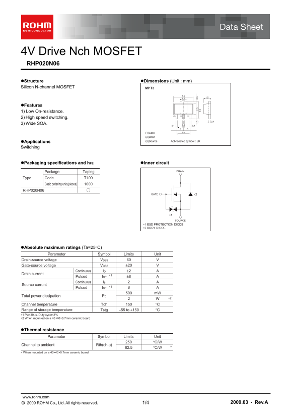
4V Drive Nch MOSFET RHP020N06 Structure Dimensions (Unit : mm) Silicon N-channel MOSFET MPT3
Features 1) Low On-resistance.
2) High speed switching.
3) Wide SOA. 0.5
(1)Gate 3.0
(2)Drain Applications (3)Source Abbreviated symbol : LR
Switching
Packaging specifications and h FE Inner circuit
Package Taping DRAIN
Type Code T100
Basic ordering unit (pieces)
RHP020N06
GATE ∗2
∗1 SOURCE
∗1 ESD PROTECTION DIODE ∗2 BODY DIODE
Absolute maximum ratings (Ta=25°C)
Parameter Symbol Limits Unit
Drain-source voltage VVDSS
Gate-source voltage ±20 VVGSS Continuous ±2 AID
Drain current
Pulsed ±8 AIDP
Continuous AIS
Source current
Pulsed AISP m W
Total power dissipation PD
Channel temperature °CTch
Range of storage temperature −55 to +150 °CTstg ∗1 Pw≤10µs, Duty cycle≤1% ∗2 When mounted on a 40 40 0.7mm ceramic board+
Thermal resistance
Parameter Symbol Limits Unit
Channel to ambient Rth(ch-a)
∗ When mounted on a 40 40 0.7mm ceramic board+
www.rohm.com ○c 2009 ROHM Co., Ltd. All rights reserved. 2009.03 - Rev.A 1/4
Page Summary Contents For ROHM RHP020N06 User Guide
Manual Details
| Brand | ROHM |
|---|---|
| Pages | 5 |
| File Size | 221.76 KB |
| Published | June 17, 2026 |
Enter the captcha to get the download link:

Frequently Asked Questions
What is the max drain-source voltage?
The maximum drain-source voltage is 60 V.
What is the on-resistance at VGS=10V?
The typical on-resistance is 150 mΩ at VGS=10V, ID=2A.
Can this MOSFET be used in medical devices?
No, it is not designed for use in medical instruments or other high-reliability safety-critical systems.