ROHM R6015FNX User Guide
Summary
This datasheet covers the ROHM R6015FNX N-channel power MOSFET in a TO-220FM fully molded package, rated for 600V drain-source voltage and 15A continuous drain current at 25°C. On-resistance is 0.35Ω maximum (0.27Ω typical) at 10V gate drive and 7.5A drain current, with forward transfer admittance of 4.5S minimum. Key dynamic characteristics include 1660pF input capacitance, 1110pF output capacitance, and 45pF reverse transfer capacitance. Gate threshold voltage is 3V to 5V with gate-source volt
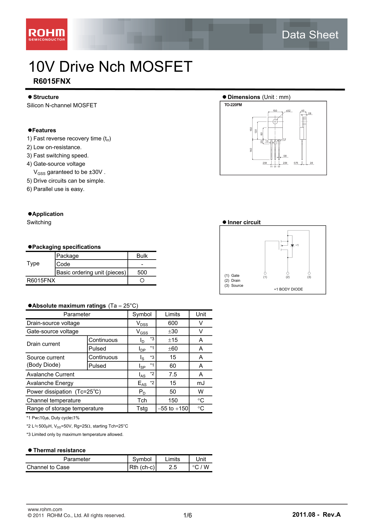
Page 1 Text Content
Data Sheet
10V Drive Nch MOSFET R6015FNX Structure Dimensions (Unit : mm)
Silicon N-channel MOSFET TO-220FM
Features
1) Fast reverse recovery time (trr) 1.2
2) Low on-resistance.
3) Fast switching speed. 0.8 2.54 0.75 2.62.54
4) Gate-source voltage
VGSS garanteed to be ±30V . 5) Drive circuits can be simple. 6) Parallel use is easy.
Application Switching Inner circuit
Packaging specifications
Package Bulk .0 2. 8.
Type Code
Basic ordering unit (pieces)
(1) Gate
R6015FNX (2) Drain (3) Source
1 BODY DIODE
Absolute maximum ratings (Ta 25°C)
Parameter Symbol Limits Unit
Drain-source voltage VDSS Gate-source voltage VGSS 30
Continuous ID 15
Drain current
Pulsed IDP *1 60 Source current Continuous IS *3 (Body Diode) Pulsed ISP *1 Avalanche Current IAS *2 7.5 Avalanche Energy EAS *2 m J
Power dissipation (Tc=25℃) PD Channel temperature Tch C Range of storage temperature Tstg 55 to 150 C *1 Pw10s, Duty cycle1% *2 L≒500H, VDD=50V, Rg=25, starting Tch=25°C *3 Limited only by maximum temperature allowed.
Thermal resistance
Parameter Symbol Limits Unit
Channel to Case Rth (ch-c) 2.5 C / W
www.rohm.com
© 2011 ROHM Co., Ltd. All rights reserved. 1/6 2011.08 - Rev.A
Page Summary Contents For ROHM R6015FNX User Guide
Manual Details
| Brand | ROHM |
|---|---|
| Pages | 7 |
| File Size | 1.23 MB |
| Published | June 22, 2026 |
Enter the captcha to get the download link:
