ROHM QS5U34 User Guide
Summary
Rohm QS5U34 transistor datasheet featuring a 1.8V drive N-channel MOSFET with integrated Schottky barrier diode in TSMT5 package. The document provides absolute maximum ratings, electrical characteristics, package dimensions, and application notes for load switching and DC-DC conversion. Target users are power electronics engineers designing low-voltage switching circuits and portable device power management systems.
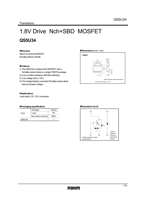
Page 1 Text Content
QS5U34
Transistors
1.8V Drive Nch+SBD MOSFET QS5U34
Structure Dimensions (Unit : mm)
Silicon N-channel MOSFET
TSMT5
Schottky Barrier DIODE
1.0MAX
Features 1) The QS5U34 combines Nch MOSFET with a 0~0.1
Schottky barrier diode in a single TSMT5 package.
2) Low on-state resistance with fast switching. 0.4 0.16
3) Low voltage drive (1.8V).
Each lead has same dimensions
4) The Independently connected Schottky barrier diode Abbreviated symbol : U34 has low forward voltage.
Applications Load switch, DC / DC conversion
Packaging specifications Equivalent circuit
Package Taping
Type Code TR
Basic ordering unit (pieces)
QS5U34
∗1 (1)Gate
(2)Source (1) (2) (3) (3)Anode ∗1 ESD protection diode (4)Cathode ∗2 Body diode (5)Drain
Page Summary Contents For ROHM QS5U34 User Guide
Manual Details
| Brand | ROHM |
|---|---|
| Pages | 5 |
| File Size | 85.68 KB |
| Published | June 16, 2026 |
Enter the captcha to get the download link:

Frequently Asked Questions
What is the maximum continuous drain current for the QS5U34?
The maximum continuous drain current is ±1.5 A.
What is the recommended application for the QS5U34?
It is designed for load switch and DC/DC conversion applications.
What is the typical on-state resistance at 1.8V gate drive?
The typical on-state resistance is 220 mΩ at ID=0.8A and VGS=1.8V.
What is the absolute maximum gate-source voltage?
The absolute maximum gate-source voltage is 10 V.