ROHM QS5K2 User Guide
Summary
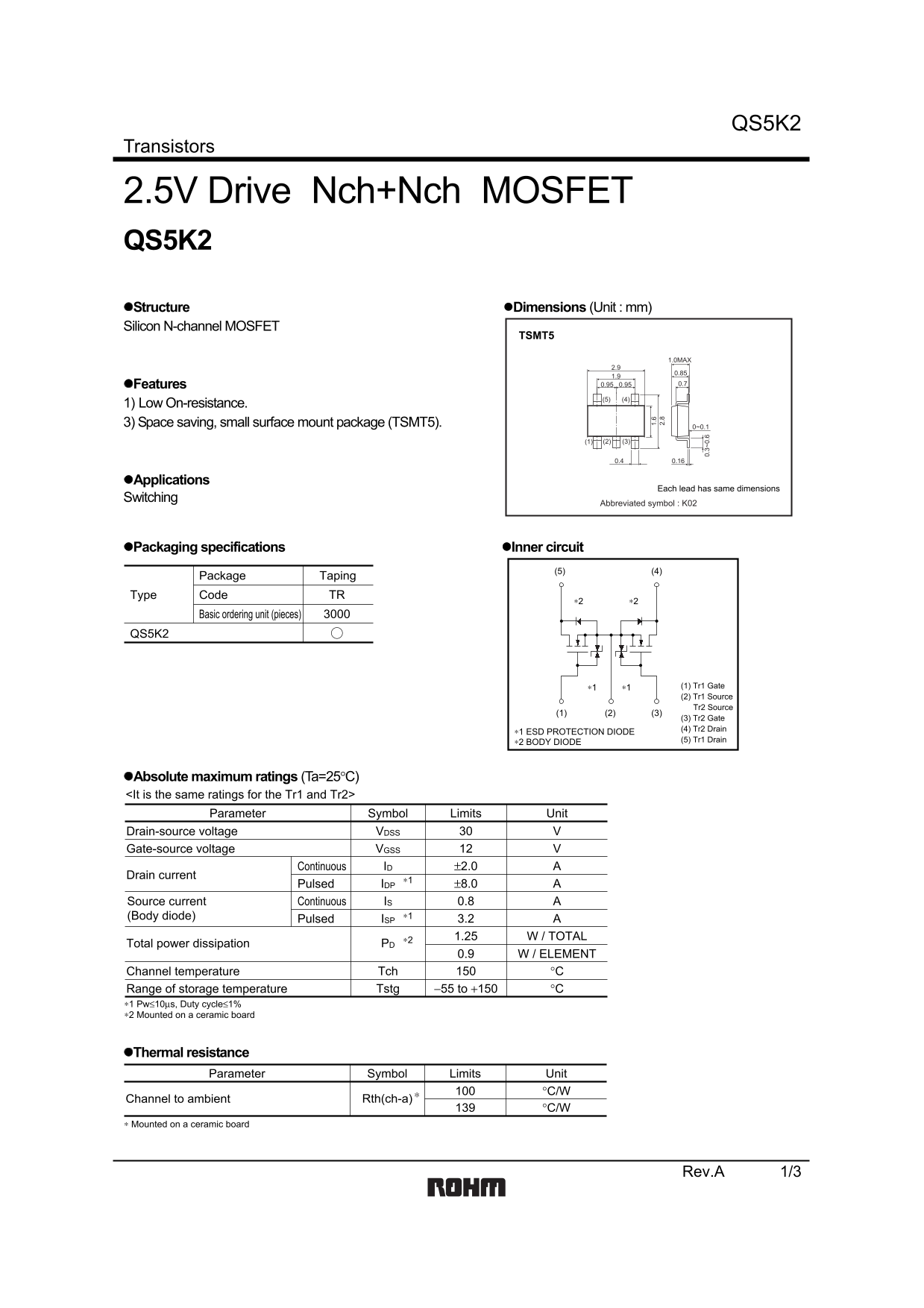
Technical datasheet for ROHM QS5K2 dual N-channel MOSFET in space-saving TSMT5 surface-mount package featuring built-in G-S protection diode and low on-resistance optimized for 2.5V gate drive voltage. Features low on-resistance (RDS(ON) = 71mΩ typical at VGS = 4.5V, ID = 2A; 76mΩ typical at VGS = 4.0V, ID = 2A; 100mΩ typical at VGS = 2.5V, ID = 2A; 110mΩ typical at VGS = 2.5V, ID = 2A), compact TSMT5 package saving PCB area in high-density assemblies, and built-in ESD protection diode between g
Page 1 Text Content
QS5K2
Transistors
2.5V Drive Nch+Nch MOSFET QS5K2 Structure Dimensions (Unit : mm) Silicon N-channel MOSFET
TSMT5
1.0MAX
Features 0.950.95 0.7
1) Low On-resistance. 3) Space saving, small surface mount package (TSMT5). 0~0.1
Applications
Each lead has same dimensions
Switching
Abbreviated symbol : K02
Packaging specifications Inner circuit
Package Taping
Type Code TR
Basic ordering unit (pieces)
QS5K2
∗1 ∗1 (1) Tr1 Gate (2) Tr1 Source
Tr2 Source 0. 3~ 0.
(3) Tr2 Gate (4) Tr2 Drain
∗1 ESD PROTECTION DIODE
∗2 BODY DIODE (5) Tr1 Drain
Absolute maximum ratings (Ta=25°C) <It is the same ratings for the Tr1 and Tr2>
Parameter Symbol Limits Unit
Drain-source voltage VVDSS Gate-source voltage VVGSS Continuous ±2.0 AID
Drain current
Pulsed ±8.0 AIDP Source current Continuous 0.8 AIS
(Body diode) ∗1
Pulsed 3.2 AISP ∗2 1.25 W / TOTAL
Total power dissipation PD
W / ELEMENT0.9 Channel temperature °CTch
Range of storage temperature −55 to +150 °CTstg
∗1 Pw≤10µs, Duty cycle≤1% ∗2 Mounted on a ceramic board
Thermal resistance
Parameter Symbol Limits Unit
Channel to ambient Rth(ch-a)
∗ Mounted on a ceramic board
Rev.A 1/3
Page Summary Contents For ROHM QS5K2 User Guide
Manual Details
| Brand | ROHM |
|---|---|
| Pages | 4 |
| File Size | 62.45 KB |
| Published | June 22, 2026 |
Enter the captcha to get the download link:

Frequently Asked Questions
What is the maximum drain current (ID) this MOSFET can handle?
The continuous Drain current is specified as $\pm 2.0 \text{ A}$, and the pulsed rating is $\pm 8.0 \text{ A}$.
What is the recommended total power dissipation (PD)?
The maximum specified total power dissipation is $0.9 \text{ W}$ per element.
How does the thermal resistance affect ambient temperature?
The channel to ambient thermal resistance ($R_{\theta(\text{ch-a})}$) is listed as $139^{\circ}\text{C/W}$ when mounted on a ceramic board.
What is the gate-source threshold voltage ($V_{GS(th)}$)?
The typical gate threshold voltage ($V_{GS(th)}$) ranges from $0.5 \text{ V}$ to $1.5 \text{ V}$.