ROHM DTC114TE User Guide
Summary
Discover high-performance NPN digital transistors in the DTC114T series, designed for robust switching, inverter, interface, and driver circuit applications. Featuring built-in biasing resistors, these semiconductors simplify circuit design by enabling easy configuration without external components. This manual provides comprehensive technical documentation, covering detailed electrical characteristics, absolute maximum ratings, packaging specifications, and guidelines necessary for implementing fail-safe electronic equipment ranging from audio visual to industrial control units. Ideal for professional hardware engineers seeking reliability and efficiency in their designs.
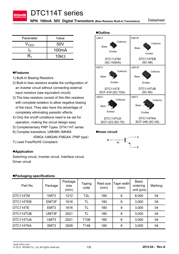
Page 1 Text Content
DTC114T series
Datasheet
NPN 100m A 50V Digital Transistors (Bias Resistor Built-in Transistors)
l Outline Parameter Value VMT3 EMT3F
Collector
Collector
VCEO 50V IC 100m A
Emitter
Emitter
DTC114TM DTC114TEB (SC-105AA) (SC-89)
EMT3 UMT3F
Collector Collector
l Features 1) Built-In Biasing Resistors
2) Built-in bias resistors enable the configuration of Emitter Emitter
an inverter circuit without connecting external
DTC114TE DTC114TUB input resistors (see equivalent circuit). SOT-416 (SC-75A) (SC-85)
UMT3 SMT3
3) The bias resistors consist of thin-film resistors
Collector Collector
with complete isolation to allow negative biasing of the input. They also have the advantage of
Emitter
completely eliminating parasitic effects. Emitter
4) Only the on/off conditions need to be set for
DTC114TUA DTC114TKA operation, making the circuit design easy. SOT-323 (SC-70) SOT-346 (SC-59)
5) Complementary PNP Types :DTA114T series
6) Complex transistors :UMH8N /IMH8A l Inner circuit
/EMG4 /UMG4N /FMG4A (PNP type) 7) Lead Free/Ro HS Compliant.
l Application Switching circuit, Inverter circuit, Interface circuit, Driver circuit
l Packaging specifications
Package Basic
Taping Reel size Tape width
Part No. Package size ordering Marking
code (mm) (mm)
(mm) unit (pcs)
DTC114TM VMT3 T2L 8,000 DTC114TEB EMT3F TL 3,000 DTC114TE EMT3 TL 3,000 DTC114TUB UMT3F TL 3,000 DTC114TUA UMT3 T106 3,000 DTC114TKA SMT3 T146 3,000
www.rohm.com © 2012 ROHM Co., Ltd. All rights reserved. 1/9 2012.04 - Rev.A
Page Summary Contents For ROHM DTC114TE User Guide
Manual Details
| Brand | ROHM |
|---|---|
| Pages | 10 |
| File Size | 741.20 KB |
| Published | June 02, 2026 |
Enter the captcha to get the download link:

Frequently Asked Questions
What types of circuits are these transistors suitable for?
Applications include switching, inverter, interface, and driver circuits.
Are the transistors lead free or RoHS compliant?
Yes, the components are Lead Free/RoHS Compliant.
Can these units operate in negative biasing configurations?
Yes, the bias resistors allow for complete isolation to enable negative biasing.
What is the maximum continuous operating temperature (Tj)?
The junction temperature range (Tj) is -55 to +150 °C.