ROHM DTA015TUB User Guide
Summary
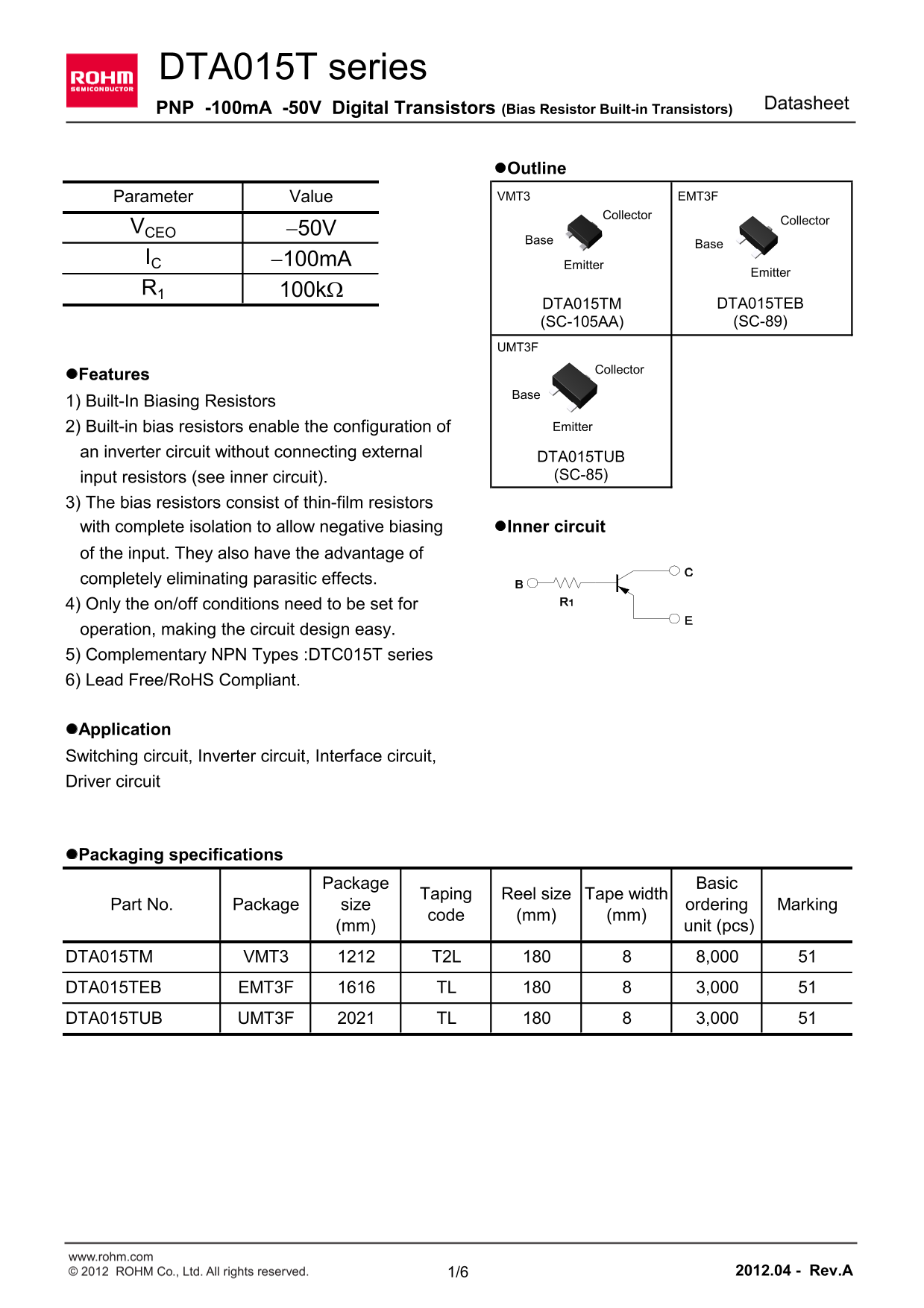
The DTA015T series are advanced PNP Digital Transistors featuring built-in biasing resistors, simplifying the design of complex circuits like inverters and interface drivers. This manual provides comprehensive technical documentation, including absolute maximum ratings, detailed electrical characteristics, and dimensional specifications for reliable integration into low-power switching and signal control applications. Ideal for electronic designers seeking to simplify circuit architecture while maintaining high performance.
Page 1 Text Content
DTA015T series
Datasheet
PNP -100m A -50V Digital Transistors (Bias Resistor Built-in Transistors)
l Outline Parameter Value VMT3 EMT3F
Collector
Collector
VCEO -50V IC -100m A
Emitter
Emitter
DTA015TM DTA015TEB (SC-105AA) (SC-89)
UMT3F
Collector
l Features 1) Built-In Biasing Resistors
2) Built-in bias resistors enable the configuration of Emitter
an inverter circuit without connecting external
DTA015TUB input resistors (see inner circuit). (SC-85)
3) The bias resistors consist of thin-film resistors with complete isolation to allow negative biasing l Inner circuit of the input. They also have the advantage of completely eliminating parasitic effects. 4) Only the on/off conditions need to be set for operation, making the circuit design easy. 5) Complementary NPN Types :DTC015T series 6) Lead Free/Ro HS Compliant.
l Application Switching circuit, Inverter circuit, Interface circuit, Driver circuit
l Packaging specifications
Package Basic
Taping Reel size Tape width
Part No. Package size ordering Marking
code (mm) (mm)
(mm) unit (pcs)
DTA015TM VMT3 T2L 8,000 DTA015TEB EMT3F TL 3,000
UMT3F TL 3,000 51DTA015TUB
www.rohm.com © 2012 ROHM Co., Ltd. All rights reserved. 1/6 2012.04 - Rev.A
Page Summary Contents For ROHM DTA015TUB User Guide
Manual Details
| Brand | ROHM |
|---|---|
| Pages | 7 |
| File Size | 513.21 KB |
| Published | July 07, 2026 |
Enter the captcha to get the download link:

Frequently Asked Questions
How does the built-in bias resistor design simplify circuit integration?
The built-in resistors enable configuration of an inverter circuit without needing external input resistors, simplifying circuit design by eliminating parasitic effects.
What types of high-reliability equipment must I avoid using this product in?
This device is not suitable for applications requiring extremely high reliability, such as medical instruments, aerospace machinery, or nuclear controllers.
What are the key electrical limits concerning Collector Current and Voltage?
The package supports a Collector current (I_C) of up to -100 mA and withstands a Collector-base voltage up to -50 V.