ROHM 2SD2702 User Guide
Summary
This manual details the 2SD2702 transistors, designed for general purpose low-frequency amplification. It covers absolute maximum ratings, electrical characteristics, and application specifications, serving as a technical reference for engineers and designers.
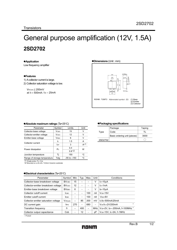
Page 1 Text Content
2SD2702
Transistors
General purpose amplification (12V, 1.5A) 2SD2702
Application Dimensions (Unit : mm)
Low frequency amplifier
Features 1) A collector current is large. 2) Collector saturation voltage is low.
VCE(sat) 200m V at IC = 500m A / IB = 25m A
ROHM : TUMT3 Abbreviated symbol : ES (1) Base
(2) Emitter (3) Collector
Absolute maximum ratings (Ta=25°C) Packaging specifications
Parameter Symbol Limits Unit Package Taping 0. 2M ax
VCBO VCollector-base voltage
Type Code TL
VCEO VCollector-emitter voltage
Basic ordering unit (pieces)
VEBO VEmitter-base voltage
2SD2702
IC 1.5
Collector current
ICP ∗1
PC WPower dissipation
Tj °CJunction temperature Tstg −55 to +150 °CRange of storage temperature
∗1 Single pulse, PW=1ms ∗2 Mounted on a 25×25× 0.8mm Ceramic substratet
Electrical characteristics (Ta=25°C)
Parameter Symbol Min. Typ. Max. Unit Conditions
BVCBO IC=10µACollector-base breakdown voltage BVCEO IC=1m ACollector-emitter breakdown voltage BVEBO IE=10µAEmitter-base breakdown voltage ICBO n A VCB=15VCollector cutoff current
Emitter cutoff current n A VEB=6VIEBO
VCE(sat) m V IC/IB=500m A/25m ACollector-emitter saturation voltage h FE VCE/IC=2V/200m ADC current gain f T MHz VCE=2V, IE=−200m A, f=100MHz Transition frequency Cob p F VCB=10V, IE=0A, f=1MHz Collector output capacitance
∗ Pulsed
Rev.B 1/2
Page Summary Contents For ROHM 2SD2702 User Guide
Manual Details
| Brand | ROHM |
|---|---|
| Pages | 3 |
| File Size | 70.39 KB |
| Published | June 15, 2026 |
Enter the captcha to get the download link:

Frequently Asked Questions
What is the maximum collector current for the 2SD2702?
The DC collector current is 1.5 A, and a single pulse (PW=1ms) allows up to 3 A.
What are the typical hFE (DC current gain) values?
At VCE=2V and IC=200mA, hFE ranges from 270 to 680.
What is the collector-emitter saturation voltage?
At IC=500mA and IB=25mA, VCE(sat) is typically 85 mV, maximum 200 mV.
What is the operating junction temperature range?
Junction temperature Tj is 150°C maximum; storage temperature ranges from -55°C to +150°C.
What is the package type for the 2SD2702?
It comes in a TUMT3 package (base, emitter, collector) with taping packaging, 3000 pieces per reel.