ROHM 2SD2153 User Guide
Summary
Ideal for signal amplification, this datasheet details the high-gain amplifier transistor (2SD2153). It provides comprehensive technical specifications, including key electrical characteristics, saturation voltages, and absolute maximum ratings under varied operating conditions. This manual is an essential resource designed for electronic engineers and circuit designers who require reliable components for building robust amplified systems.
Page 1 Text Content
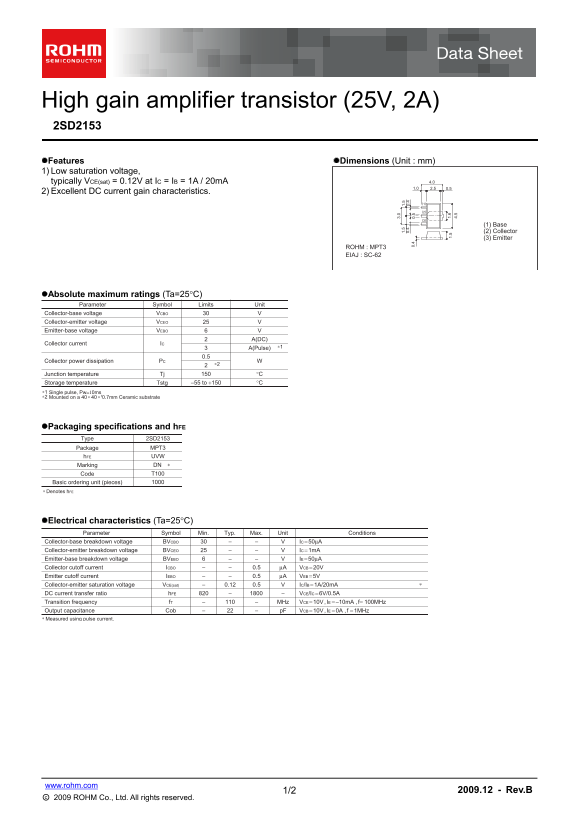
High gain amplifier transistor (25V, 2A) 2SD2153 Features Dimensions (Unit : mm) 1) Low saturation voltage,
typically VCE(sat) = 0.12V at IC = IB = 1A / 20m A 4.0 2.51.0 0.5
2) Excellent DC current gain characteristics.
(1) Base (2) Collector (3) Emitter
ROHM : MPT3 EIAJ : SC-62
Absolute maximum ratings (Ta=25C)
Parameter Symbol Limits Unit
Collector-base voltage VCBO Collector-emitter voltage VCEO Emitter-base voltage VEBO
A(DC)
Collector current IC
A(Pulse) ∗1
Collector power dissipation PC
Junction temperature Tj °C Storage temperature Tstg −55 to +150 °C
Single pulse, Pw=10ms ∗1 ∗2 Mounted on a 40 40 t0.7mm Ceramic substrate+ 3.
Packaging specifications and h FE
Type 2SD2153
Package MPT3 1.
h FE UVW 4.
Marking DN Code T100
Basic ordering unit (pieces) Denotes h FE∗
Electrical characteristics (Ta=25C)
Parameter Symbol Min. Typ. Max. Unit Conditions
Collector-base breakdown voltage BVCBO IC = 50μA
Collector-emitter breakdown voltage BVCEO IC = 1m A Emitter-base breakdown voltage BVEBO IE = 50μA
Collector cutoff current ICBO 0.5 μA VCB = 20V Emitter cutoff current IEBO 0.5 μA VEB = 5V
Collector-emitter saturation voltage VCE(sat) 0.12 0.5 IC/IB = 1A/20m A DC current transfer ratio h FE VCE/IC = 6V/0.5A
Transition frequency f T MHz VCE = 10V , IE = −10m A , f= 100MHz Output capacitance Cob p F VCB = 10V , IE = 0A , f = 1MHz
Measured using pulse current.∗
www.rohm.com
1/2 2009.12 - Rev.B
○c 2009 ROHM Co., Ltd. All rights reserved.
Page Summary Contents For ROHM 2SD2153 User Guide
Manual Details
| Brand | ROHM |
|---|---|
| Pages | 3 |
| File Size | 158.86 KB |
| Published | June 19, 2026 |
Enter the captcha to get the download link:

Frequently Asked Questions
What safety measures must I implement when using this product?
You must implement safety measures like derating, redundancy, fire control, and fail-safe designs.
Are the electrical characteristics provided absolute guarantees?
No. The data do not indicate the worst value or guaranteed value, and values based on specific lots may vary.
What is the required mounting substrate for this component?
It must be mounted on a 40 x 40 x 0.7mm Ceramic substrate.