ROHM 2SD1834 User Guide
Summary
This medium power transistor is a robust electronic component engineered for reliable switching and high current gain in various circuits. The accompanying technical manual provides exhaustive details, including absolute maximum ratings, detailed electrical characteristics (such as $h_{FE}$ and breakdown voltages), and performance graphs for precise circuit design validation. It is essential documentation for electronics engineers and designers building professional equipment, including communication devices, industrial controls, and audio/visual systems.
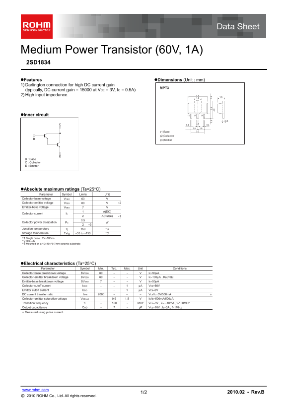
Page 1 Text Content
Medium Power Transistor (60V, 1A) 2SD1834 Features Dimensions (Unit : mm) 1) Darlington connection for high DC current gain
(typically, DC current gain = 15000 at VCE = 3V, IC = 0.5A) 2) High input impedance. 4.5
Inner circuit (3)(2)(1)
1.51.5 (1)Base 3.0
(2)Collector (3)Emitter
: Base : Collector : Emitter
Absolute maximum ratings (Ta=25C)
Parameter Symbol Limits Unit
Collector-base voltage VCBO Collector-emitter voltage VCES ∗2 Emitter-base voltage VEBO
A(DC) 1. 0.
Collector current IC 4. 02.
A(Pulse) ∗1
Collector power dissipation PC
Junction temperature Tj °C Storage temperature Tstg −55 to +150 °C
∗1 Single pulse Pw=100ms ∗2 RBE=0Ω
∗3 Mounted on a 40×40× t0.7mm ceramic substrate
Electrical characteristics (Ta=25C)
Parameter Symbol Min. Typ. Max. Unit Conditions
Collector-base breakdown voltage BVCBO IC=50μA
Collector-emitter breakdown voltage BVCEO IC=100μA , RBE=0Ω
Emitter-base breakdown voltage BVEBO IE=50μA Collector cutoff current ICBO μA VCB=60V Emitter cutoff current IEBO μA VEB=6V DC current transfer ratio h FE VCE/IC=3V/500m A Collector-emitter saturation voltage VCE(sat) 0.9 1.5 IC/IB=500m A/500μA Transition frequency f T MHz VCE=5V , IE= −10m A , f=100MHz
Output capacitance Cob p F VCE=10V , IE=0A , f=1MHz
∗ Measured using pulse current.
www.rohm.com
1/2 2010.02 - Rev.B
○c 2010 ROHM Co., Ltd. All rights reserved.
Page Summary Contents For ROHM 2SD1834 User Guide
Manual Details
| Brand | ROHM |
|---|---|
| Pages | 3 |
| File Size | 130.90 KB |
| Published | June 01, 2026 |
Enter the captcha to get the download link:

Frequently Asked Questions
What is the typical DC current gain of this transistor?
The datasheet specifies a typical DC current gain (MPT3) of 15000 at VCE = 3V and IC = 0.5A.
What are the absolute maximum ratings for voltage and power dissipation?
The collector-emitter voltage (VCES) and collector-base voltage (VCBO) limits are both 60V, and the maximum collector power dissipation (PC) is 2W.
Can this transistor handle high frequencies?
Its transition frequency (fT) is rated at -150 MHz, tested under conditions of VCE=5V and IE=-10mA.
Is there a requirement for mounting the device during operation?
Yes, under absolute maximum ratings testing, the unit must be mounted on a 40×40× 0.7mm ceramic substrate.